
GEOM-360 · Lesson 4 of 12 · 20 min
Single-beam echo sounders
The reservoir's deep pool, near the dam, is too deep for the green lidar that mapped the margins last autumn. It covers about four hectares, reaches about twelve metres, and has a soft, muddy bottom of settled silt. The district needs it surveyed to close the capacity table, and it needs a check line through the 3 to 6 m band where the lidar and the sonar overlap. Ines decides that a single-beam echo sounder on the district's aluminium boat is the right tool: the area is small, the bottom is smooth, the budget is modest, and a single-beam sounder with two frequencies can say something about the soft sediment that a multibeam would not. Grant and Theo take the boat out on a cold October morning.
How an echo sounder works
A single-beam echo sounder sends a short pulse of sound from a transducer mounted on or through the hull and listens for the echo from the bottom. A transducer is a piezoelectric element that converts electrical energy into sound and back. The sounder measures the two-way travel time \(t\) and converts it to range with the sound speed \(c\), then adds the transducer's depth below the water line (its draft) and any fixed correction to give the depth below the water surface:
The pulse is formed into a beam whose width depends on the transducer's size compared with the wavelength: a larger transducer, or a higher frequency, gives a narrower beam. Survey sounders commonly use 200 kHz with beams of 3° to 10°, often paired with a lower frequency such as 24 to 33 kHz with a wider beam. The sounder's electronics detect the echo by its amplitude rising above a threshold or, in better systems, by analysing the echo's shape, and they report a depth many times a second.
Calibration: bar check and index
Two things can make a sounder read wrongly even when the electronics work perfectly: a sound speed setting that does not match the water, and a fixed offset from the electronics, the transducer's mounting or the measured draft. The traditional check is the bar check: a plate or bar suspended on marked cables is lowered beneath the transducer to known depths, and the sounder's readings are compared with the true depths. A straight-line fit of reading against true depth gives a slope, which reveals a sound speed error, and an intercept, which reveals the index error. In deeper water, where a bar is impractical, the sound speed is measured with a profiler and the index is checked by comparison with a lead line or a known depth at a wharf.
import math
# Single-beam echo sounder on the survey boat in the reservoir's deep pool
c_set = 1462.0        # sound speed entered in the sounder this morning, m/s
draft = 0.42          # transducer depth below the water line, m

# Bar check: a plate lowered to known depths below the transducer
bar = [(2.0, 2.05), (4.0, 4.08), (6.0, 6.10), (8.0, 8.12), (10.0, 10.15)]  # (true, sounder reading) m
n = len(bar); sx = sum(b for b, _ in bar); sy = sum(r for _, r in bar)
sxx = sum(b * b for b, _ in bar); sxy = sum(b * r for b, r in bar)
k = (n * sxy - sx * sy) / (n * sxx - sx * sx); i0 = (sy - k * sx) / n
c_true = c_set / k
print(f"bar check fit: reading = {k:.4f} x true {i0:+.3f} m")
print(f"so the water's mean sound speed is about {c_true:.1f} m/s, and the index error {i0:+.3f} m")

# Correct a raw reading of 10.62 m below the transducer
raw = 10.62
true_below = (raw - i0) / k
d = true_below + draft
print(f"raw {raw:.2f} m -> {true_below:.2f} m below the transducer -> depth {d:.2f} m below the surface")

# Footprint of the beam on a flat bottom
for f_khz, beam in ((200, 8.0), (33, 20.0)):
    r = d * math.tan(math.radians(beam / 2))
    print(f"{f_khz:3d} kHz, {beam:4.1f} deg beam: footprint diameter {2*r:.2f} m at {d:.1f} m")

# Shoal bias on a sloping bottom: the sounder reports the nearest echo inside its beam
s = math.radians(12.0)
for beam in (8.0, 20.0, 30.0):
    h = math.radians(beam / 2)
    r = d * math.cos(s) if h >= s else d * math.cos(s) / math.cos(s - h)
print(f"{beam:4.1f} deg beam on a 12 deg slope: reads {r:.2f} m, {d - r:.2f} m shallow")bar check fit: reading = 1.0120 x true +0.028 m so the water's mean sound speed is about 1444.7 m/s, and the index error +0.028 m raw 10.62 m -> 10.47 m below the transducer -> depth 10.89 m below the surface 200 kHz, 8.0 deg beam: footprint diameter 1.52 m at 10.9 m 33 kHz, 20.0 deg beam: footprint diameter 3.84 m at 10.9 m 8.0 deg beam on a 12 deg slope: reads 10.75 m, 0.13 m shallow 20.0 deg beam on a 12 deg slope: reads 10.65 m, 0.23 m shallow 30.0 deg beam on a 12 deg slope: reads 10.65 m, 0.24 m shallow
The fit shows the sounder reading 1.2 percent long with an index of +0.028 m. A reading proportionally too long means the sound speed entered in the sounder, 1,462 m/s, is too high: the cold deep water carries sound at only about 1,445 m/s. Corrected, a raw reading of 10.62 m becomes 10.47 m below the transducer and 10.89 m below the surface after the 0.42 m draft. Uncorrected, the deep pool would have been charted 0.13 m too deep across its whole area, enough to overstate the reservoir's storage by several thousand cubic metres. Theo sets the sounder to the measured speed for the rest of the day and repeats the bar check in the afternoon, when the surface has warmed slightly.
Footprint and the shoal bias of a beam
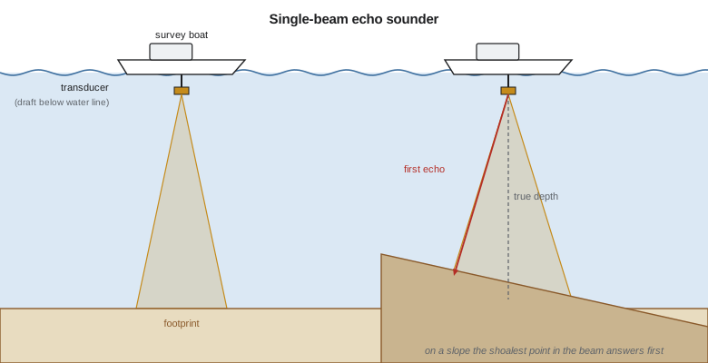
A beam of finite width does not measure a point. It insonifies an area of the bottom, the footprint, whose diameter on a flat bottom is \(2d\tan(\beta/2)\) for a beam of full width \(\beta\). The 8° beam at 200 kHz has a footprint about 1.5 m across at 10.9 m depth; the 20° beam at 33 kHz, about 3.8 m. The sounder reports the range of the first strong echo within the footprint, which on a flat bottom is the point directly below. On a sloping bottom, however, the nearest point is upslope of the vessel, and the sounder reports a depth shallower than the true depth beneath it. The bias grows with the beam width and the slope, until the beam is wide enough to contain the point closest to the transducer, after which it reads the perpendicular distance to the slope.
On the 12° side slopes of the deep pool, the narrow beam reads 0.13 m shallow and the wide beams about 0.24 m shallow. The bias is in the safe direction for navigation, which is one reason single-beam surveys served charting well for decades, but it is a real error for a volume survey. It also means that a single-beam sounder cannot detect a small object reliably: a boulder that occupies a small part of a wide footprint may return an echo, and the depth reported may be the boulder's, but the position assigned to it is the centre of the footprint, which may be metres away.
Two frequencies and soft bottoms
High-frequency sound reflects from the top of soft sediment: the water-sediment boundary where the fluffy layer begins. Low-frequency sound penetrates further and reflects from a firmer layer below. In a reservoir with decades of settled silt, the two frequencies can disagree by tens of centimetres or more, and both answers are useful: the high frequency marks the top of the water column the operators can use, and the low frequency points toward the consolidated material. For navigation in harbours with fluid mud, port authorities define a nautical depth based on a density threshold of the mud rather than on any acoustic reflection. Northshore's harbour survey uses the high-frequency surface; the reservoir report gives both and explains the difference.
Survey lines and what lies between them
Because a single-beam sounder measures only beneath the vessel, a survey consists of parallel lines with gaps between them, plus cross lines run at right angles to check consistency. Line spacing is chosen from the purpose and the expected variability of the bottom: perhaps 10 to 25 m for a reservoir capacity survey, wider for a broad reconnaissance, closer for a dredging survey in a narrow channel. Cross lines, typically at five to ten times the main line spacing, give independent depths where they intersect the main lines; the differences at crossings measure the survey's internal consistency and expose errors in sound speed, tide or timing.
The bottom between lines is not measured; it is interpolated. A depth surface built from single-beam lines is a model, and the hydrographer must say how confident the model is, especially where it matters. Modern standards treat single-beam surveys as offering limited coverage and do not accept them as proof that an area is clear of objects. That is why a single-beam survey of the deep pool is acceptable for a capacity table, where small objects do not matter, and why the berth survey uses multibeam with an object search.
Single-beam sounders today
Single-beam sounders remain in wide use. They are cheap, simple, light and easy to calibrate; they work from small boats, kayaks and uncrewed vessels; and in shallow rivers and lakes they are often the practical choice. Dredging contractors use them on their own vessels for quick checks between full surveys. Many reservoirs and rivers have long records of single-beam cross-sections, and repeating the same sections with the same method is the best way to measure change. Some systems add a sub-bottom profiler, a low-frequency sounder that images layers below the seabed, useful for estimating sediment thickness or finding rock beneath a dredging area.
For the St. Mary River intake, Grant runs single-beam cross-sections every 10 m over a 200 m reach, with the boat's GNSS antenna mounted directly above the transducer. In the shallow riffles he finishes the sections on foot with an RTK pole, so each section joins the bank survey without a gap. Lesson 11 uses these sections to compute the flow area at the intake.
Field procedure
The day's procedure is simple but disciplined. Before leaving the dock, Grant checks the transducer mounting, measures the draft with the boat loaded as it will be during the survey, and confirms that the GNSS receiver, the sounder and the logging software share a common time. Theo casts the profiler and performs the bar check. During the survey, the logging software records time, position, the raw depth and, where available, the digitized echo. Grant watches the echogram, the scrolling display of echo strength against time, for signs of trouble: a doubled bottom from a second reflection, a weak or broken trace over weeds or gas, or a sudden jump that may be a fish or a timing glitch. At the end of the day the bar check is repeated and the gauge is read.
Worked problem
Footprint and slope bias
A sounder with a 10° beam surveys a 15° slope where the true depth beneath the vessel is 8.0 m. Find the footprint diameter on a flat bottom at that depth and the depth the sounder will read on the slope.
Show solution
- \[D = 2 \times 8.0 \times \tan 5^\circ = 1.40\ \text{m}\]
- \text{The half-beam (5°) is less than the slope (15°), so the nearest echo comes from the upslope beam edge.}
- \[r = \frac{d\cos s}{\cos(s - \beta/2)} = \frac{8.0\cos 15^\circ}{\cos 10^\circ} = 7.85\ \text{m}\]
Answer: The footprint is 1.40 m across, and the sounder reads 7.85 m, 0.15 m shallow.
Common mistakes
MistakeSkipping the bar check because the sound speed was entered from a table.
InsteadMeasure; the real water rarely matches the table.
MistakeMeasuring the draft with an empty boat.
InsteadMeasure it loaded as surveyed; the hull sits lower with crew and fuel.
MistakeTreating interpolated depths between lines as measured.
InsteadState the line spacing and the limits of the model.
MistakeUsing a wide beam on steep slopes without correction.
InsteadExpect a shoal bias that grows with beam width and slope.
Summary and key terms
- A single-beam sounder converts two-way travel time to depth with the sound speed, plus draft and index.
- The bar check reveals sound speed (slope) and index (intercept) errors.
- Footprints grow with depth and beam width; slopes produce a shoal bias.
- Two frequencies distinguish the top of soft sediment from firmer layers.
- Single-beam surveys have gaps between lines; cross lines check consistency.
- They remain the practical tool for rivers, small reservoirs and repeat sections.
- Transducer
- A device converting electrical energy to sound and back.
- Bar check
- Calibration by lowering a plate to known depths beneath the transducer.
- Index error
- A fixed offset in the sounder's depth reading.
- Footprint
- The area of the bottom insonified by a beam.
- Echogram
- A display of echo strength against time along the track.
- Cross line
- A line run across the main lines to check consistency.
- Sub-bottom profiler
- A low-frequency sounder that images layers below the seabed.
Practice problems
Work each problem on paper first, then reveal the answer to check.
A bar check gives reading = 0.990 x true + 0.010 m with the sounder set to 1,450 m/s. What is the real sound speed?
Show answer
About 1,465 m/s.
What is the footprint diameter of a 6° beam at 20 m depth?
Show answer
About 2.10 m.
Why can a single-beam survey not prove an area is clear of small objects?
Show answer
It measures only beneath the vessel, leaving gaps between lines.
Two frequencies read 9.40 m and 9.85 m over a reservoir bottom. What does the difference suggest?
Show answer
About 0.45 m of soft sediment above a firmer layer.
What do cross-line differences measure?
Show answer
The survey's internal consistency.
Lesson quiz · 5 questions
Score 60% or more to complete this lesson.
Create a free account to save your progress, take quizzes and earn a certificate.