
GAS-130 · Lesson 7 of 12 · 23 min
Electric motors on gas appliances
▶ Video coming soon A video version of this lesson is on the way.
The Garfield Avenue bungalow, where Bayline had replaced a cracked vent connector in October and a gas main in November, called again on the second Sunday of November. The furnace was lighting, the house was getting no warmer, and the high-limit code was flashing. Rosa and Jonah found the burners shutting off every few minutes, and the blower, instead of running, was humming and barely turning. Rosa switched off the power, locked the switch and turned the blower wheel by hand with a stick. It spun freely. "Free wheel, humming motor," she said. "That's a motor that can't start itself. Nine times in ten it's the capacitor. Let's find out if this is the tenth."
Every modern gas appliance has at least one electric motor and many have several: the draft inducer or venter that moves flue gases, the blower that moves air through a furnace, the circulator that moves water through a boiler, fans on rooftop units and unit heaters, and the compressor and fan of an air conditioner sharing the system. This lesson explains how these motors work, how to read their nameplates and how to test them. It stays with single-phase motors of the kind found in houses and small commercial buildings.
How an electric motor turns
An electric motor works by magnetic forces. Like magnetic poles repel and unlike poles attract. In an AC induction motor, the stationary part, the stator, has coils of wire that produce a magnetic field when current flows. The rotating part, the rotor, is a cylinder of iron laminations with bars of aluminum or copper cast through it, joined at the ends, like a squirrel cage. The stator's changing field induces currents in the rotor bars, and those currents make the rotor's own magnetic field, which is pulled round by the stator's field. The rotor turns slightly slower than the field, which is why a motor nameplate shows a speed such as 1,075 revolutions per minute rather than an exact 1,200.
A single-phase supply makes a field that pulses back and forth but does not rotate on its own. A single-phase motor needs a way to give its field a rotating push, at least to start. The different single-phase motor types are, in effect, different ways of doing that, and each has its own way of failing.
Shaded-pole motors
The simplest single-phase motor is the shaded-pole motor. A copper ring, the shading coil, around part of each stator pole delays the field in that part of the pole, enough to create a weak rotating effect. Shaded-pole motors are cheap and reliable but inefficient and weak at starting. They are found on small fans, older draft inducers, some condensate pumps and older bathroom fans. They have no capacitor and no starting switch, so the usual faults are worn bearings that slow or stall the rotor, and an open winding, which shows OL across the two leads with power off.
Permanent split capacitor motors
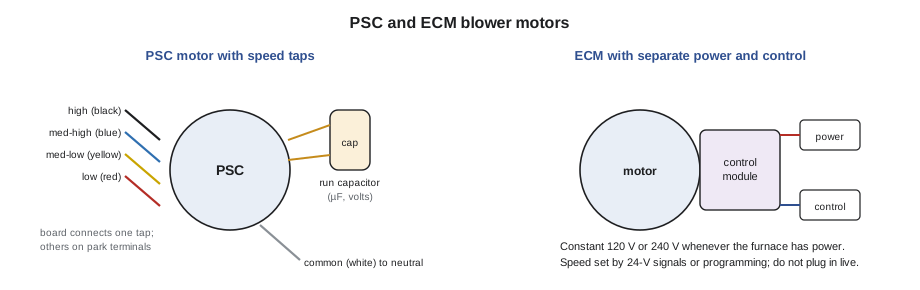
The permanent split capacitor (PSC) motor is the workhorse of older furnace blowers, many inducers and many condenser fans. It has two windings: the main or run winding, connected directly across the supply, and the auxiliary or start winding, connected in series with a run capacitor. The capacitor shifts the timing of the current in the auxiliary winding, so the two windings' fields peak at different moments and together make a rotating field. Unlike some larger motors, the capacitor stays in the circuit all the time the motor runs.
Many PSC blower motors have multiple speed taps: several leads, often coloured black for high, blue for medium-high, yellow or orange for medium-low and red for low, that connect to different points on the main winding. The control board connects the heating speed tap and the cooling speed tap to the supply as needed, and unused taps are parked on dummy terminals. Only one speed tap may be connected to the supply at a time. Connecting two at once shorts part of the winding and destroys the motor.
Capacitors
A capacitor stores electric charge on two metal plates separated by an insulator. In an AC circuit it charges and discharges with every cycle, which is what shifts the current in a PSC motor's auxiliary winding. Capacitors are rated in microfarads (µF) and by voltage. A furnace blower capacitor might be marked 10 µF, 370 VAC, with a tolerance such as plus or minus 6 in 100. The microfarad value must match the motor's specification; the voltage rating must be at least that of the original, and a higher voltage rating is acceptable. Dual capacitors in air conditioners have three terminals, for the compressor, the fan and the common connection.
Capacitors fail by losing capacitance, by shorting, or by opening. A capacitor with a domed or bulging top, or with oil leaking from it, has failed. One that looks fine may still have lost much of its capacitance. A motor with a weak or open run capacitor hums, starts slowly or not at all, runs hot and draws high current, and trips on its internal overload, exactly as the Garfield Avenue blower was doing.
A capacitor can hold a charge after the power is removed, so it must be discharged safely before it is handled or tested. With power off and proved dead, discharge it through a resistor made for the purpose, such as a discharge tool of about 20,000 Ω, connected across its terminals for a few seconds. Do not short a capacitor's terminals with a screwdriver: the spark can damage the terminals and the capacitor, and on a large capacitor it is a burn hazard. Then disconnect at least one lead and measure the capacitance with the meter's capacitance function.
Worked problem
Is the capacitor within tolerance?
The Garfield Avenue blower's capacitor is marked 7.5 µF ± 6 in 100, 370 VAC. After discharging it and removing its leads, Jonah measures 4.1 µF. What range is acceptable, and is this capacitor good?
Show solution
- Find the allowed variation:
- \[7.5 \times \frac{6}{100} = 0.45 \ \mu\text{F}\]
- Find the acceptable range:
- \[7.5 - 0.45 = 7.05 \ \mu\text{F} \quad \text{to} \quad 7.5 + 0.45 = 7.95 \ \mu\text{F}\]
- Compare the reading:
- \[4.1 \ \mu\text{F} < 7.05 \ \mu\text{F}\]
Answer: The capacitor has lost almost half its capacitance and must be replaced with a 7.5-µF capacitor rated 370 VAC or higher. It explains the humming: without enough phase shift, the motor could not start itself.
Electronically commutated motors
Most new furnaces use an electronically commutated motor (ECM) for the blower, and many use one for the inducer. An ECM has a permanent-magnet rotor and an electronic control module, usually mounted on the back of the motor, that switches the stator windings in sequence to turn it. Because the electronics control the field directly, an ECM is much more efficient than a PSC motor, especially at low speeds, and its speed can be set precisely.
ECMs come in two broad kinds. Constant-torque motors, sometimes called by a manufacturer's model name, have several 24-volt input terminals; energizing one of them selects a programmed torque setting, a little like a speed tap. Constant-airflow or variable-speed motors are programmed for the furnace and adjust their speed to deliver a set airflow against changing duct resistance, taking their commands from the control board through a communication or signal cable. Either way, an ECM has a constant 120-volt (or 240-volt) supply that is present whenever the furnace has power, even when the motor is not running, and separate low-voltage control connections.
Testing an ECM follows its design. First confirm the high-voltage supply at the motor's power plug. Then confirm that the control signal the motor needs is present: 24 volts at the selected tap for a constant-torque motor, or the signal the manufacturer describes for a variable-speed motor, sometimes with a diagnostic tool the manufacturer supplies. If both are correct and the motor does not run, the motor or its module has failed. Do not measure the windings' resistance as you would on a PSC motor without the manufacturer's procedure, and never unplug or plug in an ECM's power connector with the power on: the inrush to the module's electronics can damage it. Wait for the time the manufacturer gives after switching off, so the module's internal capacitors discharge.
Reading a motor nameplate
A motor's nameplate gives the information needed to test it and to choose a replacement: voltage, full-load amps (FLA) or rated amps, horsepower or watts, speed in revolutions per minute, rotation as seen from a stated end, frequency and phase, frame size, the capacitor size for a PSC motor, and whether it is thermally protected. Most small motors on gas appliances have an automatic-reset thermal protector inside the windings, which opens when the motor overheats and resets when it cools. A motor that runs a while, stops, then starts again later is often cycling on its internal protector because of a mechanical or electrical problem.
Running current is the most useful check. With the motor running at the speed and load it normally sees, clamp one supply conductor and compare the reading with the nameplate FLA. A current close to or a little below FLA is normal. A current well above FLA points to low voltage, a weak capacitor, failing bearings, the wrong speed tap or a mechanical load the motor was not meant to drive. On the common forward-curved blower wheel found in furnaces, a current well below normal often means the airflow is restricted: a blocked filter or closed registers mean the wheel moves less air, does less work and draws less current. That surprises many apprentices, and it is why amps alone never tell the whole story.
Worked problem
Comparing running current with the nameplate
After the new capacitor is fitted, the Garfield Avenue blower starts at once. Its nameplate shows 1/3 hp, 115 V, 5.8 FLA. Jonah clamps the supply lead on heating speed and reads 5.1 A. How does this compare with the nameplate, and about how many watts does 1/3 hp represent?
Show solution
- Compare the measured and rated current:
- \[\frac{5.1}{5.8} \approx 0.88\]
- Convert horsepower to watts, using 746 W per horsepower:
- \[\frac{1}{3} \times 746 \approx 249 \text{ W}\]
Answer: The blower draws about 88 in every 100 parts of its full-load current, normal for heating speed with a clean filter. The 249 W is the motor's rated mechanical output; its electrical input is higher because of losses and power factor.
| Motor type | Where found | Starting method | Common faults |
|---|---|---|---|
| Shaded-pole | Small fans, older inducers, condensate pumps | Shading coils on the poles | Worn bearings, open winding |
| PSC | Older blowers, inducers, condenser fans | Run capacitor in the auxiliary winding | Weak or open capacitor, bearings, wrong speed tap |
| ECM, constant-torque | Newer blowers | Electronic control module | Module failure, missing 24-V tap signal, moisture |
| ECM, variable-speed | High-efficiency furnaces and air handlers | Electronic control module with programmed airflow | Module failure, communication or programming fault |
Choosing a replacement motor
When a motor is replaced, the safest choice is the exact part from the appliance manufacturer. A universal replacement motor must match the original in voltage, horsepower, speed, rotation, frame and mounting, shaft size and capacitor; for an inducer, its performance must match the original, because the venting and the pressure switch were set up for it. Changing a blower motor's speed or horsepower changes the furnace's airflow and therefore its temperature rise, which the appliance's rating plate limits. A furnace with too little airflow overheats its heat exchanger, trips its limit and can crack. Lesson 9 shows how the motor connects into the wiring diagram, and the later course on appliance controls covers airflow setup.
Back at Garfield Avenue
With the new capacitor in, the blower started cleanly, the heat exchanger stopped tripping the limit, and the temperature rise settled inside the range on the rating plate. Rosa had Jonah also check the filter, which was clean, and listen to the motor bearings, which were quiet. On the work order Jonah wrote the old capacitor's reading, 4.1 µF against 7.5 µF marked, the new running current, 5.1 A against 5.8 FLA, and the temperature rise. "Write the numbers," Rosa said. "Next time somebody comes here, they'll know what normal looked like."
Common mistakes
MistakeShorting a capacitor's terminals with a screwdriver.
InsteadDischarge it through a resistor tool after proving the circuit dead.
MistakeConnecting two speed taps of a PSC motor to the supply.
InsteadConnect one speed tap at a time; park the others on dummy terminals.
MistakeReplacing a capacitor with a different microfarad value.
InsteadMatch the µF rating; the voltage rating may be the same or higher.
MistakePlugging in an ECM's power connector with the power on.
InsteadSwitch off, wait as the manufacturer says, then connect or disconnect.
MistakeAssuming low blower amps means a healthy motor.
InsteadOn a forward-curved blower, low amps can mean restricted airflow.
Summary and key terms
- Induction motors turn because a rotating magnetic field in the stator drags the rotor round.
- Shaded-pole motors use shading coils and are simple but weak.
- PSC motors use a run capacitor in the auxiliary winding and often have several speed taps, only one connected at a time.
- Capacitors are rated in µF and volts, must be discharged safely before testing, and fail by losing capacitance, shorting or opening.
- ECMs use electronics and a permanent-magnet rotor, have a constant line-voltage supply and separate control signals, and must not be plugged in live.
- Compare running current with nameplate FLA, remembering that restricted airflow lowers the current of a forward-curved blower.
- Match replacements to the original.
- Stator
- The stationary part of a motor, carrying the windings.
- Rotor
- The rotating part of a motor.
- PSC motor
- A permanent split capacitor motor with a run capacitor in its auxiliary winding.
- Run capacitor
- A capacitor that stays in a motor circuit while it runs, shifting the auxiliary winding current.
- Microfarad
- One millionth of a farad, the unit used to rate motor capacitors.
- ECM
- An electronically commutated motor, with a permanent-magnet rotor and electronic control.
- Full-load amps
- The current a motor is rated to draw at its full rated load.
- Thermal protector
- A switch inside a motor that opens when the windings overheat.
Practice problems
Work each problem on paper first, then reveal the answer to check.
What does a humming PSC motor that will not start usually need?
Show answer
A new run capacitor, after checking that the wheel turns freely.
How should a capacitor be discharged?
Show answer
Through a resistor tool across its terminals, after proving the circuit dead.
A capacitor is marked 5 µF ± 6 in 100. What is the lowest acceptable reading?
Show answer
5 − 0.3 = 4.7 µF.
Why might a forward-curved blower draw low current?
Show answer
Restricted airflow reduces the work it does.
What supply is always present at an ECM when the furnace is powered?
Show answer
Its line-voltage supply, 120 V or 240 V.
Lesson quiz · 5 questions
Score 60% or more to complete this lesson.
Create a free account to save your progress, take quizzes and earn a certificate.