
GAS-130 · Lesson 12 of 12 · 24 min
Case study: a furnace that will not start
▶ Video coming soon A video version of this lesson is on the way.
On Saturday, November 14, 2026, the coldest morning of the autumn so far, Priya Nair took a call at 7:10 from a homeowner in a townhouse on Concession Street on the Hamilton Mountain. The furnace had stopped some time in the night, the thermostat screen was blank, and the house was down to 15 °C. The furnace was a six-year-old high-efficiency model that Bayline did not install but had serviced the year before. Priya sent Rosa Delgado and Jonah Clarke, and Rosa repeated her instruction from the duplex call: Jonah would lead, she would watch, and nothing would be touched without a reason.
This lesson follows that call from start to finish, using the method from lesson 11 and the ideas from every lesson before it. It is a real-world sequence, not a checklist to memorize: the point is the reasoning at each step.
Step 1: Gather information
At the door, Jonah asked the questions first. When did the heat stop? The owners had gone to bed at eleven with the house warm and woke at six to a cold house and a blank thermostat. Had anything changed? Yes: a renovation contractor had finished the basement the previous week, framing and drywalling a new family room around the utility room, and had put up a ceiling bulkhead to hide ducts and wiring. Had anyone touched the furnace? The owner had switched the furnace switch off and on at six, with no result. Was there any smell of gas or any carbon monoxide alarm? No.
In the utility room, Jonah looked before touching. The furnace's door was in place. The status light on the control board, visible through the small window in the door, was off: not flashing a code, simply dark. The furnace switch at the bottom of the stairs was on. The breaker in the panel was on. The filter was clean. The condensate trap was full and draining. The vent and air intake terminals outside were clear of snow. Nothing obvious.
Step 2: What the symptoms say
A blank thermostat and a dark board light are a strong pair of clues. The thermostat was a powered model that needed 24 volts between R and C. The board's light runs from the same 24-volt supply. Both dark at once pointed away from the thermostat and the gas side, and towards the supply: either no 120 volts to the furnace, no 24 volts from the transformer, or something taking the 24-volt supply down. Jonah said this out loud, and Rosa nodded.
Step 3: Prove the supplies
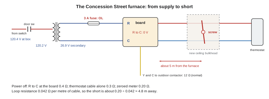
Jonah removed the furnace door, which opened the door switch and killed power to the furnace's internals, as lesson 6 described. To take live readings with the door off, he used the method in Bayline's procedure, holding the door switch closed only for the duration of the readings with a clip made for the job, keeping his hands clear of the inducer and blower, and wearing his safety glasses. At the furnace junction box he read 120.4 volts hot to neutral, 120.3 volts hot to ground and 0.2 volts neutral to ground: a healthy supply, correct polarity and a sound ground, as lesson 10 described.
At the transformer, he read 120.2 volts across the primary leads and 26.9 volts across the secondary leads, a little above 24 volts because the transformer was barely loaded, as lesson 5 explained. Then he moved the meter to the board's R and C terminals: 0 volts. The transformer was making 24 volts, but it was not reaching the board's R terminal. Between the transformer's secondary and R on the board there was one component: the board's 3-amp blade fuse. With power off, locked out and proved dead, Jonah pulled the fuse and measured it: OL. The fuse was open.
Step 4: Do not replace the fuse yet
A new fuse costs very little, and the temptation is to push one in and see what happens. Jonah did not, and Rosa told him later that this was the most important decision of the call. A blown fuse is evidence that something drew more current than 3 amps from the 24-volt circuit. If that something is still there, a new fuse will blow at once, or, if it is an intermittent short, the next time the conditions repeat, perhaps at three in the morning on a colder night. Lesson 5 said it plainly: find the short first.
The 24-volt circuit had three branches outside the board's own components: the thermostat cable to the hall upstairs, the outdoor cable to the condensing unit's contactor coil, and the furnace's own gas valve and safety chain. With power still off, Jonah measured the resistance between R and C at the board terminals with all field wiring connected: 0.4 Ω. A healthy 24-volt circuit, with the thermostat not calling, should read far higher than that, because the only paths from R to C are through the thermostat's own electronics and through coils of many ohms. 0.4 Ω meant a dead short.
Step 5: Isolate the short
Jonah now split the circuit into its branches, in the spirit of half-splitting. He disconnected the outdoor cable's two conductors from Y and C at the board and measured across them: about 12 Ω, the resistance of the contactor coil at the far end, which was normal. He reconnected them. He disconnected the thermostat cable's R and C conductors from the board and measured R to C on the board side: a high resistance, several kilohms, through the board's own circuits. The short was not in the board. He measured between the thermostat cable's red and blue conductors, the ones used for R and C: 0.3 Ω.
The short was in the thermostat cable or the thermostat. Upstairs, Jonah removed the thermostat from its base and measured again from the furnace end: still 0.3 Ω between red and blue. With the thermostat off the wall, the only thing left was the cable itself. Somewhere between the furnace and the hall, its red and blue conductors were touching each other.
Worked problem
Estimating how far away the short is
Jonah zeroed his meter with the leads shorted together, so the lead resistance was removed, and measured 0.20 Ω between the red and blue conductors from the furnace end. Using 2.1 Ω per 100 m for each 18 AWG conductor, about how far along the cable is the short?
Show solution
- The current path runs out on one conductor and back on the other, so the loop resistance per unit of cable length is twice that of one conductor:
- \[2 \times \frac{2.1}{100} = 0.042\ \Omega \text{ per m}\]
- Divide the measured resistance by the loop resistance per unit length:
- \[\frac{0.20}{0.042} \approx 4.8 \text{ m}\]
Answer: The short is roughly 5 m from the furnace along the cable. Measurements this small are rough, because contact resistance at the probes and the short itself add a little, but they told Jonah where to look: the cable left the utility room through the new bulkhead about that distance away.
Step 6: Find the root cause
Jonah followed the cable's route. It left the furnace, ran along a joist to the edge of the utility room and disappeared into the new drywall bulkhead the renovation contractor had built over the family room, roughly 4 to 6 m from the furnace. Rosa asked the owner whether anyone had mentioned problems with the thermostat since the basement was finished. The owner remembered that on Thursday evening, the day the drywall was screwed up, the screen had flickered once.
With the owner's permission, Rosa cut a small inspection hole in the bulkhead at the place where the cable ran close to the framing. A drywall screw had been driven through the edge of the thermostat cable where it was stapled to the side of a joist. The screw had pierced the jacket and bridged the red and blue conductors, but only lightly: the circuit had survived for two days with a high-resistance contact, until the cold night, when the house's framing shrank a little, the screw made solid contact, the 24-volt circuit was shorted, and the fuse did its job and opened.
That explained everything: the blank thermostat, the dark board, the open fuse, and the timing. The root cause was not the fuse, the board or the transformer; it was mechanical damage to a Class 2 cable during the renovation, where the cable had been left in a place that framing and fasteners would reach.
Step 7: Repair
The damaged cable could not be properly spliced inside a finished ceiling, because splices must remain accessible and the damage might not be the only one. Rosa and Jonah ran a new 18/5 thermostat cable by a different route: through the joists of the unfinished part of the utility room, up through the interior wall cavity behind the furnace room into the hall, and to the thermostat base, keeping it away from the framing edges where future fasteners would go, and stapling it lightly with insulated staples. They left the old cable in place, cut back and taped at both ends and labelled "damaged, do not use".
Jonah connected R, C, W, Y and G at both ends, and checked each conductor for continuity end to end and for no continuity to its neighbours before connecting the thermostat. With power still off, he measured R to C at the board with the new cable connected and the thermostat on its base: several kilohms, as it should be. Only then did he fit a new 3-amp fuse of the same type and rating as the original.
Step 8: Verify
With power restored, the board light came on with its normal slow flash, and Jonah read 26.4 volts R to C at the board and 26.1 volts at the thermostat base. The thermostat started and connected to the house's Wi-Fi. He set a heating call and watched the full sequence: inducer, pressure switch, igniter, gas valve, flame, blower. During the call he measured the gas valve coil current with ten turns through the clamp, 0.48 A, and the R to C voltage under load, 25.2 volts. He checked the gas side as the start-up sheet required, including the manifold pressure and the temperature rise, both within the rating plate's ranges, and ran three complete cycles. He also ran a short cooling call to confirm the outdoor contactor pulled in, then switched the thermostat back to heat.
Worked problem
Checking the transformer load after the repair
The furnace transformer is rated 40 VA. During the heating call, the board, its relays and the thermostat together draw an estimated 10 VA, and the gas valve draws 0.48 A at 25.2 V. What is the total load on the transformer, and does it have reserve?
Show solution
- Find the gas valve VA:
- \[25.2 \times 0.48 \approx 12.1 \text{ VA}\]
- Add the other loads:
- \[12.1 + 10 = 22.1 \text{ VA}\]
- Compare with the rating:
- \[\frac{22.1}{40} \approx 0.55\]
Answer: The transformer runs at a little over half its rating during a heat call, so the short had not been an overload problem, and the fuse had protected the transformer. Jonah noted that the transformer looked and smelt normal and had held 26.9 V unloaded, so it did not need replacing.
Step 9: Record and explain
On the work order, Jonah wrote the supply readings, the transformer readings, the open fuse, the 0.4-Ω short measured at the board, the 0.3-Ω and 0.20-Ω readings on the cable, the estimated distance, the location and cause of the damage, the new cable's route, and the verification readings, with the time of each. Rosa added a note recommending that the owners ask the renovation contractor to patch the inspection hole and to check that no other cables had been pierced in the new ceiling, and a note that the furnace had been left operating normally.
The owner asked why a little screw could stop the whole furnace. Jonah explained it the way this course has built it up. The thermostat and the furnace's controls run on a small 24-volt circuit from a transformer. The screw connected the two sides of that circuit together, a short circuit, so a large current flowed, and the fuse opened to protect the transformer and the board, exactly as it was designed to. With the fuse open, the board and the thermostat had no power, so nothing could call for heat. The repair was to remove the short and restore the protection, and the job was not finished until the furnace had proved it could run normally again.
What the call shows
Every lesson in the course appeared on this call. Ohm's law explained why a short draws a large current and how resistance could estimate the distance to the fault. Series and parallel circuits explained why one shorted branch took down the whole 24-volt supply and how disconnecting branches isolated it. Household power, polarity and grounding were checked first because they underpin everything. Safe testing practice decided when power was on and when it was off. The transformer and its fuse behaved as lesson 5 described. The thermostat's need for a C wire made the blank screen the first clue. And the troubleshooting method turned a cold, blank house into a sequence of readings, each of which narrowed the possibilities until only one was left. Above all, the call shows the value of finding the cause before replacing the part: a technician who had simply fitted a new fuse might have left with the furnace running, and come back to a blown fuse, an angry customer and a cold house on the next cold night.
Common mistakes
MistakeReplacing an open fuse to see whether it holds.
InsteadMeasure R to C with power off and find the short before fitting a new fuse.
MistakeSuspecting the control board because the light is off.
InsteadProve line voltage, the transformer and the fuse first.
MistakeSplicing a damaged thermostat cable inside a finished ceiling.
InsteadRun a new cable by a protected route; splices must stay accessible.
MistakeStopping when the fuse holds.
InsteadVerify the full sequence, including cooling, and record the readings.
MistakeLeaving the owner without an explanation.
InsteadExplain the cause and recommend checking the rest of the renovation.
Summary and key terms
- A blank thermostat and a dark board light pointed to the 24-volt supply.
- Supplies were proven first: 120 V with correct polarity and ground, 120 V on the transformer primary, 26.9 V on its secondary, but 0 V at R on the board because the 3-amp fuse was open.
- Instead of replacing the fuse, Jonah measured 0.4 Ω R to C with power off, isolated the branches, and found the short in the thermostat cable.
- The resistance of the shorted loop estimated the distance to the fault, and a drywall screw from the basement renovation was found through the cable.
- A new cable was run by a protected route, the circuit was checked before a new fuse went in, and the full sequence was verified and recorded.
- Dead short
- A short circuit with almost no resistance, drawing very high current.
- Loop resistance
- The combined resistance of the outgoing and return conductors of a circuit.
- Zeroing the meter
- Removing the test leads' own resistance from a reading, often with a relative mode.
- Accessible splice
- A joint in wiring that can be reached for inspection without damaging the building.
- Verification
- Running the appliance through complete cycles and readings to prove the repair.
Practice problems
Work each problem on paper first, then reveal the answer to check.
Why did Jonah not replace the fuse straight away?
Show answer
A blown fuse means a short or overload; a new fuse would blow again until the cause was found.
What R to C resistance did he measure with power off, and what did it mean?
Show answer
0.4 Ω: a dead short in the 24-volt circuit.
How did he show the short was in the thermostat cable?
Show answer
By disconnecting branches and measuring each; with the thermostat removed, the cable still read 0.3 Ω.
What caused the short?
Show answer
A drywall screw driven through the cable during the basement renovation.
Why was the cable replaced rather than spliced?
Show answer
A splice inside a finished ceiling would not be accessible, and the cable might be damaged elsewhere.
Lesson quiz · 5 questions
Score 60% or more to complete this lesson.
Create a free account to save your progress, take quizzes and earn a certificate.