
GAS-130 · Lesson 11 of 12 · 23 min
Electrical troubleshooting methods
▶ Video coming soon A video version of this lesson is on the way.
After the carbon monoxide incident at the duplex on Barton Street in October, the owner had replaced the old water heater with a power-vented model that Bayline installed. In the first week of November the upstairs tenant called: twice in a week there had been no hot water in the morning, and both times it came back on its own by lunchtime. Rosa sent Jonah with a simple instruction. "You lead this one. I'll watch and keep my hands in my pockets. Don't touch a part until you can tell me why you're touching it."
By this point in the course, the pieces are all in place: Ohm's law, series and parallel circuits, household power, safe meter use, transformers, switches and relays, motors, thermostats, diagrams, grounding and polarity. This lesson puts them together into a method. Good troubleshooters are not the ones who know the most parts; they are the ones who work in a fixed order, measure instead of guessing, and stop when they have found the cause rather than the first thing that looks wrong.
A method in ten steps
Bayline teaches a ten-step method, set out in the figure below. It is not the only method in the trade, but every good one shares its shape: gather information, observe, think with the diagram, test from the supply towards the fault, isolate, find the root cause, repair, verify and record.
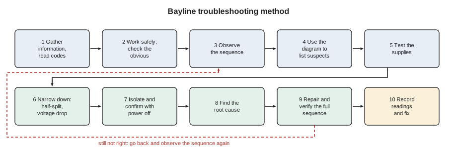
1 and 2: Gather information and check the obvious
Start before you open the appliance. Ask the customer what happened, when, and what has changed: new work in the house, a power outage, a storm, a renovation, a new thermostat. Ask whether the problem is constant or intermittent, and whether it follows the weather or the time of day. Read the appliance's fault code or flashing light before you switch anything off, because many controls clear their stored code when power is removed. Look for the service history, which may be in a tag on the appliance or in Bayline's records.
Then check the obvious, safely. Is the appliance switched on? Is the breaker on? Is the thermostat calling, set to the right mode and showing a display? Is the gas valve on and the gas supply present? Is the filter blocked, the condensate drain backed up, the vent terminal covered in snow? A surprising number of calls end here, and the ones that do still deserve a careful check of why, such as why the drain backed up.
3: Observe the sequence
Watch the appliance try to run. Lesson 9 showed that every appliance follows a sequence. Note how far it gets: does the inducer start, does the pressure switch close, does the igniter glow, does the gas valve open, does flame appear and stay, does the blower start? The point where the sequence stops is the strongest clue you will get, because it tells you which rung on the ladder diagram is not being completed. On an intermittent fault, you may need to run several cycles, or wait for the conditions that cause it.
4: Use the diagram to list suspects
With the stopping point identified, go to the ladder diagram. Find the load that did not come on and list everything in series with it: switches, relay contacts, connectors, the board output. That list is your set of suspects. Anything not on it can be set aside for now. A technician who skips this step tends to test the parts that are easiest to reach rather than the parts that could cause the symptom.
5: Test the supplies
Before testing any individual suspect, prove the supplies: line voltage at the appliance, with the polarity and ground correct as lesson 10 described, and 24 volts R to C at the control board. A sagging or missing supply makes everything downstream behave strangely. A flame failure caused by reversed polarity, a relay chattering because of low control voltage or a board resetting because of a loose neutral will send a technician who skipped this step in the wrong direction for an hour.
6: Narrow down by half-splitting and voltage drop
With the supplies proven and the suspects listed, measure to find which one is open or faulty. Two techniques do most of the work. Voltage drop testing, from lesson 2, measures across each component with the circuit powered: a closed switch or good connection shows almost zero volts, an open shows the full circuit voltage, and a poor connection shows something in between. Point-to-reference testing keeps one meter lead on a fixed reference, such as C on the 24-volt side or neutral on the line-voltage side, and moves the other lead along the circuit from the supply towards the load. The voltage is present up to the open and absent beyond it.
Half-splitting makes either technique faster. Instead of testing every point in order, test in the middle of the suspect chain. If the voltage is present there, the fault is in the second half; if not, it is in the first half. Then test the middle of the half that contains the fault, and so on. Each test halves the number of suspects, so the fault is found in very few readings even in a long chain.
Worked problem
How many readings does half-splitting need?
A boiler's safety chain has 8 series devices between R and its gas valve: two limits, a low-water cut-off, a flow switch, a pressure switch, a rollout switch, a blocked-vent switch and a manual-reset switch. One of them is open. Testing one device after another, how many readings might be needed in the worst case? How many with half-splitting?
Show solution
- One after another, the worst case is testing every device but the last:
- \[8 - 1 = 7 \text{ readings}\]
- Half-splitting halves the suspects with each reading:
- \[8 \rightarrow 4 \rightarrow 2 \rightarrow 1\]
- Count the halvings:
- \[2^3 = 8 \Rightarrow 3 \text{ readings}\]
Answer: Half-splitting finds the open device in 3 readings instead of up to 7. On a long chain the saving is larger: 16 devices take 4 readings instead of up to 15.
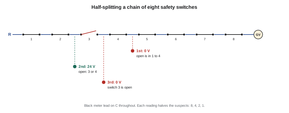
Worked problem
Point-to-reference readings
On the duplex water heater, the control's pressure-switch circuit runs from its 24-V output through a connector, the pressure switch and a second connector back to the control's input. With the vent motor running, Jonah holds the black lead on C and reads 24.6 V at the control's output, 24.6 V on the supply side of the pressure switch, 24.5 V on the far side of the pressure switch, and 11.8 V at the control's input pin. What do the readings show, and what is the voltage drop across the suspect part?
Show solution
- The voltage is full up to and through the pressure switch, so the switch itself is closed.
- The voltage falls between the far side of the switch and the control input, across the second connector:
- \[24.5 - 11.8 = 12.7 \text{ V}\]
Answer: About 12.7 V is being lost across one connector, a high-resistance connection, not an open switch. The control sees only 11.8 V and, on a warm day or when the connector shifts, decides the pressure switch has opened.
7: Isolate and confirm with power off
When the measurements point to a part, confirm it before replacing anything. Switch off, lock out and prove dead. Disconnect the suspect part at one end, so that other circuits do not affect the reading, and measure its resistance or continuity. Inspect connectors for corrosion, heat discolouration, loose or spread terminals and broken wires inside the insulation near the crimp. Compare a coil's or winding's resistance with the manufacturer's figure. On a motor, check capacitance, bearings and whether the shaft turns freely.
Be careful with substitution, swapping in a new part to see if it helps. It can confirm a diagnosis, but used as the diagnosis it wastes parts, money and time, and can hide the real fault. A new control board fitted to a furnace whose real problem was a shorted thermostat cable will blow its own fuse, or worse, its own circuit, within minutes. Control boards are replaced last, after every input to them has been checked, and only when the measurements show the board is not doing what its inputs say it should.
8: Find the root cause
Every failed part failed for a reason. A blown fuse points to a short; a burnt contactor to age, a failing compressor or low voltage; a failed inducer motor to age or to water reaching its bearings from a vent problem; a tripped limit to low airflow. Before closing up, ask why the part failed and whether the cause is still there. Replacing a part without removing the cause guarantees a callback, and in some cases, such as a rollout switch tripped by a blocked heat exchanger or a pressure switch defeated by a blocked vent, a safety hazard.
9: Repair and verify
Repair with the correct part, connected according to the wiring diagram. Then verify the whole sequence, not just the part you fixed: run the appliance through complete cycles, confirm each step happens in order, check the safety controls still work as intended, and take the readings that show the appliance is operating correctly, such as supply voltage, control voltage, motor currents and, on the gas side, pressures and combustion. If anything is still wrong, go back to step 3 and observe again.
10: Record
Write down what you found, what you measured and what you did, with the actual numbers. The record helps the next technician, protects Bayline if something goes wrong later, and builds the technician's own experience. A note that says "replaced pressure switch connector, 12.7 V drop across old connector, 0.1 V after repair, ran 5 cycles" is worth far more than "fixed".
Intermittent faults
The hardest faults are the ones that are not happening when you arrive. They are usually caused by something that changes with conditions: a connection that opens when it warms up or cools down, a component that fails when wet, a supply voltage that sags when a neighbour's equipment starts, or a vent that ices up only in a particular wind. The method still works, but observation takes longer. Ask exactly when it happens; read the fault history, which many controls store; inspect connections closely and wiggle them gently while measuring; warm or cool a suspect part within its rating; and leave a written note asking the customer to record the time and any code if it happens again. Never leave an appliance running with a safety control bypassed to "see if it does it again".
| Symptom | First measurements | Common causes |
|---|---|---|
| Nothing happens on a call; no display | Line voltage at the appliance, 24 V R to C | Switch or breaker off, open fuse, failed transformer, door switch |
| Inducer runs, nothing more | Voltage across the pressure switch; vent and drain | Blocked vent or drain, failed pressure switch, high-resistance connection |
| Igniter glows, no gas valve | Voltage across the safety chain and at the valve | Open safety switch, valve coil, board output |
| Burner lights then shuts off | Polarity, ground, flame signal | Reversed polarity, poor ground, dirty flame sensor |
| Blower hums, will not start | Capacitor, free wheel, current | Failed run capacitor, seized bearings |
| Board fuse blows | Resistance R to C with field wiring disconnected | Shorted thermostat or outdoor cable, shorted coil |
Back at the duplex
Jonah read the water heater's fault history before touching anything: three stored pressure-switch faults, all in the early morning. He ran a cycle and watched it complete normally. He then took the point-to-reference readings in the example, found the 12.7-volt drop across the connector, switched off, locked out, proved dead and pulled the connector. Its terminals were green with corrosion. A drip of condensate from a sagging section of the vent's condensate line had been landing on it, worst on cold mornings when condensate production was highest. He told Rosa what he wanted to do and why. She nodded. He replaced the connector with the manufacturer's harness, re-supported the condensate line so it drained away from the controls, ran five cycles and measured 0.1 volt across the new connector. On the work order he wrote the readings, the root cause and the repair. "That's the method," Rosa said. "Next week we see if you can do it on one I haven't seen first."
Common mistakes
MistakeSwitching the power off before reading the fault code.
InsteadRead and record codes first; many controls clear them on power loss.
MistakeTesting whichever parts are easiest to reach.
InsteadUse the diagram to list the parts that could cause the symptom.
MistakeReplacing the control board first.
InsteadProve every supply and input; replace the board last, on evidence.
MistakeStopping at the failed part.
InsteadFind out why it failed and remove the cause.
MistakeLeaving a safety control jumpered to catch an intermittent fault.
InsteadNever bypass safety controls; use fault history, close inspection and customer notes.
Summary and key terms
- Troubleshoot by a fixed method: gather information and read codes before removing power; check the obvious; observe how far the sequence gets; use the ladder diagram to list suspects; prove line voltage, polarity, ground and 24 V first; narrow down with voltage drop and point-to-reference readings, using half-splitting to save time; isolate and confirm with power off; find the root cause; repair and verify the full sequence; record the numbers.
- Use substitution only to confirm a diagnosis, and replace control boards last.
- Intermittent faults need patience, fault histories and close inspection, never bypassed safeties.
- Half-splitting
- Testing at the middle of a suspect chain so each reading halves the number of suspects.
- Point-to-reference testing
- Keeping one meter lead on a fixed reference and moving the other along the circuit.
- Voltage drop testing
- Measuring across a component under load to find opens and high resistance.
- Root cause
- The underlying reason a part failed or a fault occurred.
- Intermittent fault
- A fault that comes and goes with conditions.
- Fault code
- A code or flash pattern a control uses to report what it has detected.
Practice problems
Work each problem on paper first, then reveal the answer to check.
Why read the fault code before switching off power?
Show answer
Many controls clear their stored codes when power is removed.
How many readings does half-splitting need for 16 suspects?
Show answer
Four, because 2⁴ = 16.
What should be proven before testing individual parts?
Show answer
The line voltage, polarity and ground, and the 24-V control supply.
When is a control board replaced?
Show answer
Last, after every supply and input has been checked and the board is shown not to respond correctly.
What is the last step of the method?
Show answer
Record what was found, measured and done.
Lesson quiz · 5 questions
Score 60% or more to complete this lesson.
Create a free account to save your progress, take quizzes and earn a certificate.