
GAS-130 · Lesson 5 of 12 · 23 min
Transformers and 24-volt control circuits
▶ Video coming soon A video version of this lesson is on the way.
Luis Ferreira took Jonah along on a boiler call on Aberdeen Avenue in early November. The house had hot-water heat with zone valves, and the owner had recently finished the attic and had a heating contractor from out of town add a fifth zone. Since then the boiler had stopped twice, and this morning it would not run at all. In the boiler room Luis pointed at a small black box screwed to a junction box on the wall, with a faint smell of hot varnish around it. "That's the zone control transformer," he said. "Somebody gave it more work than it was built for. Let's prove it, and then work out what it should have been."
Almost every gas appliance with electronic controls runs its thermostat, safety switches, gas valve and relays at about 24 volts AC, supplied by a small step-down transformer. This lesson explains how a transformer works, how to read its rating, how to work out whether it is big enough, and how the 24-volt circuit is organized and protected.
Magnetism and induction
A current flowing in a wire produces a magnetic field around it. Wind the wire into a coil and the fields of all the turns add up; wind the coil on an iron core and the field becomes much stronger and is guided through the core. This is how the coil of a relay or a gas valve pulls in its armature or plunger, as the next lesson describes.
The reverse also happens. When the magnetic field through a coil changes, a voltage is induced in the coil. A steady field induces nothing; only a changing field does. Alternating current provides a field that is changing all the time, reversing 120 times a second. Put two coils on the same iron core, feed one with AC, and the changing field it makes induces an AC voltage in the other. That is a transformer. There is no electrical connection between the two coils, only the magnetic link through the core, which is also why a transformer will not work on DC.
Primary, secondary and the turns ratio
The coil connected to the supply is the primary winding, and the coil connected to the load is the secondary winding. The voltage induced in each turn of wire is the same for both coils, so the voltages are in the same ratio as the numbers of turns. A transformer with fewer turns on its secondary than its primary is a step-down transformer; one with more is a step-up transformer.
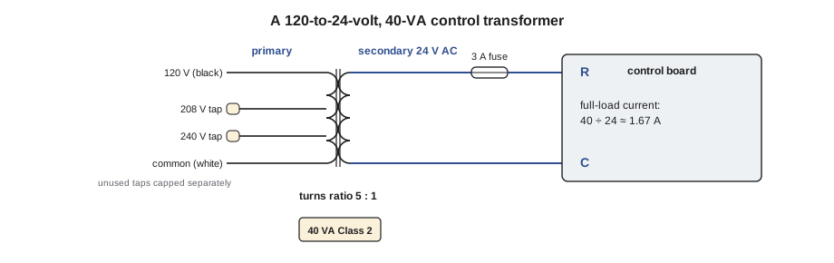
A furnace control transformer steps 120 volts down to 24 volts, a ratio of 5 to 1. The ignition transformer of an older spark-ignition boiler, or the spark generator of a commercial burner, steps the voltage up to several thousand volts to jump a spark gap. Many control transformers have a multi-tap primary, with separate leads for 120, 208 and 240 volts, so that the same part can be used on different supplies. The unused leads must be capped individually and taped; using the wrong tap produces the wrong secondary voltage.
Worked problem
Secondary voltage from the turns ratio
Suppose a control transformer has 1,000 turns on its primary and 200 turns on its secondary, and the primary is connected to 120 V. What is the secondary voltage? What would it be if the supply sagged to 108 V?
Show solution
- Find the ratio of turns:
- \[\frac{N_P}{N_S} = \frac{1000}{200} = 5\]
- Divide the primary voltage by the ratio:
- \[V_S = \frac{120}{5} = 24 \text{ V}\]
- With a sagging supply:
- \[V_S = \frac{108}{5} = 21.6 \text{ V}\]
Answer: The secondary follows the primary in proportion. A low supply means low control voltage, which can make relays chatter and gas valves open slowly, so a low 24-volt reading calls for checking the primary voltage before blaming the transformer.
VA ratings and current
A transformer is rated in volt-amperes (VA), the product of its secondary voltage and the current it can deliver continuously without overheating. Lesson 3 explained why VA rather than watts: the loads on a control transformer are coils, whose current does not stay in step with the voltage. A typical residential furnace transformer is rated 40 VA; boilers with zone valves, rooftop units and commercial equipment often use 50, 75 or 100 VA.
Ignoring the small losses inside the transformer, the VA in equals the VA out. This gives the current on each side:
A 40-VA transformer can supply 40 ÷ 24, or about 1.67 amps at 24 volts, while drawing only about a third of an amp from the 120-volt supply. Every load on the secondary, such as the gas valve coil, the board's relays, the cooling contactor coil, a humidifier solenoid, zone valves and a smart thermostat, draws part of that capacity. Exceed it and the transformer overheats; its insulation breaks down, its secondary voltage sags under load, and eventually a winding opens.
Worked problem
Sizing the zone control transformer
At the Aberdeen Avenue house, the zone panel was fed from one 40-VA transformer. Each zone valve's motor is rated 7 VA, the boiler's relay coil 5 VA, and Luis allows 3 VA for the thermostats. With all five zones calling at once, what is the load, and what size transformer is needed?
Show solution
- Add the zone valves:
- \[5 \times 7 = 35 \text{ VA}\]
- Add the other loads:
- \[35 + 5 + 3 = 43 \text{ VA}\]
- Compare with the transformer:
- \[43 \text{ VA} > 40 \text{ VA}\]
- Find the secondary current:
- \[I_S = \frac{43}{24} \approx 1.8 \text{ A}\]
Answer: With all five zones calling, the 40-VA transformer was overloaded. With four zones, the load was 36 VA and the transformer coped; the fifth zone pushed it over. Luis replaced it with a 75-VA Class 2 transformer, which also leaves room for the inrush of the zone valve motors when they start.
The 24-volt control circuit
The secondary of a furnace transformer usually runs to two terminals on the control board, marked R for the hot side and C for common. On many furnaces the C side is connected to the cabinet, so the 24-volt circuit is referenced to ground. From R, the 24 volts goes to the thermostat and comes back on the W wire to call for heat, on Y for cooling and on G for the fan. The board then energizes the inducer, checks the safety switches, lights the igniter and opens the gas valve, all from the same 24-volt supply. Lesson 8 covers the thermostat side in detail and lesson 9 reads the diagram.
The 24-volt circuit is protected by a small fuse, typically an automotive-style blade fuse of 3 or 5 amps on the control board. It protects the transformer and the board's circuit traces from a short in the field wiring, such as a thermostat cable cut by a staple or a condensing-unit cable chewed by a rodent. A blown board fuse is almost never the fault itself; it is evidence of a short or overload somewhere else, and replacing it without finding the short just blows the next fuse, or worse, the transformer.
Measuring the control circuit is simple once the layout is known. With power on, read R to C at the board: about 24 to 28 volts with no call, perhaps a volt or two less under load, is normal. If R to C reads zero, check the primary: 120 volts at the transformer primary leads but nothing at the secondary means an open transformer winding, or an open fuse if the meter is reading on the far side of it. No 120 volts at the primary means the problem is upstream: the switch, the door interlock, the breaker or the supply.
| Reading | Likely meaning | Next step |
|---|---|---|
| 120 V at primary, about 24 to 28 V R to C | Transformer and fuse are good | Move on to the thermostat and safety circuit |
| 120 V at primary, 0 V at secondary leads | Open transformer winding | Find out why it failed, then replace with the correct VA and taps |
| 24 V at secondary leads, 0 V R to C on the board | Open board fuse | Find the short before replacing the fuse |
| 0 V at primary | No supply to the transformer | Check the switch, door interlock, breaker and supply |
| Low secondary voltage under load only | Overload, or low primary voltage | Add up the VA load; measure the primary |
Class 2 circuits
Most control transformers on residential gas appliances are Class 2 transformers. A Class 2 circuit is one whose voltage and available power are limited so that it presents little risk of fire or shock: in practice, AC circuits of 30 volts or less with the power limited to about 100 VA, either by the transformer's own design or by built-in overcurrent protection. The transformer's label states that it is Class 2. Because the energy is limited, the codes allow Class 2 circuits to be wired with lighter, lower-voltage cable, such as ordinary thermostat cable, and with simpler methods than power wiring.
In the Canadian Electrical Code, Class 2 circuits are covered by Section 16, which also requires Class 2 conductors to be kept separate from power conductors, except where a barrier separates them or the code otherwise permits. ESA's residential HVAC guideline adds practical points, such as allowing approved low-voltage cable of a suitable type to run in a return-air duct to a humidifier, and allowing Class 2 joints at the furnace to be made with approved connectors outside a box if they stay accessible.
The rule that matters most on the job is the separation rule. Never run thermostat cable in the same raceway, box or bundle as 120-volt wiring unless the arrangement is specifically permitted, and never use a spare conductor in a power cable to carry a 24-volt signal. A fault between the two systems would put line voltage onto the thermostat wiring and the thermostat on the wall.
Phasing and multiple transformers
Some systems have more than one 24-volt transformer: a furnace with its own, a zone panel with another, a condensing unit with a third. Their secondaries must never be connected together unless the manufacturer's diagram shows how and the transformers are phased. Two transformers whose outputs are out of step can put 48 volts between terminals that should be at the same potential, or short one transformer against the other. Where a separate transformer is used for an accessory, it should drive the accessory through an isolating relay, as the next lesson describes, rather than share a common terminal.
The grounded side of the secondary
On many furnaces, one side of the 24-volt secondary, the C side, is connected to the cabinet, and the control board uses the cabinet as part of its reference. That has two practical consequences. First, a 24-volt conductor that chafes through its insulation and touches the cabinet is a short, not merely a ground fault, if it is the R side: the current runs straight from R to the grounded C side, the board fuse blows, and the thermostat goes blank. Second, if the transformer's C lead or its ground connection is loose, the board can behave strangely, because its reference has gone. Some controls, such as those that sense flame through the burner, need that ground reference to work at all, a point the later course on appliance controls develops.
When a replacement transformer is fitted, follow the furnace's wiring diagram for which secondary lead is grounded and do not add or remove a ground connection on a whim. A universal replacement transformer may arrive with its own grounding instructions, and the furnace's diagram takes priority for how it fits that furnace.
Back at Aberdeen Avenue
Luis had Jonah check the old transformer with power on first: 121 volts at the primary, 0 volts at the secondary. With power off, locked out and proved dead, the secondary winding read OL: open. The varnish smell was its insulation. Luis fitted the 75-VA transformer, capped the unused primary taps one by one, and had Jonah measure the secondary with all five zones calling: 25.6 volts. He then labelled the zone panel with the transformer size and the zone valve ratings, so the next contractor would know what the circuit could take.
Common mistakes
MistakeReplacing a blown board fuse and leaving.
InsteadA blown fuse means a short or overload; find it before fitting a new fuse.
MistakeReplacing a transformer with whatever VA is on the van.
InsteadAdd up the connected VA and choose a transformer with margin.
MistakeLeaving unused primary taps bare.
InsteadCap and insulate each unused tap separately.
MistakeConnecting the secondaries of two transformers together.
InsteadKeep separate transformers separate, or phase them as the manufacturer shows; use isolating relays.
MistakeRunning thermostat cable in the same box as 120-volt wiring.
InsteadKeep Class 2 wiring separate from power wiring as the code requires.
Summary and key terms
- A transformer has two coils on an iron core and works only on AC; the voltages are in the ratio of the turns, so a 5-to-1 transformer steps 120 V to 24 V.
- Transformers are rated in VA; secondary current is VA ÷ secondary voltage, so a 40-VA transformer gives about 1.67 A at 24 V.
- Add up every load to check the size.
- The 24-volt circuit runs from R through the thermostat and safety switches and returns on C, and is protected by a small board fuse whose failure points to a short elsewhere.
- Class 2 circuits are limited to about 30 V and 100 VA, may use thermostat cable, and must be kept separate from power wiring.
- Never tie separate transformers together.
- Transformer
- A device that changes AC voltage using two coils linked by a magnetic core.
- Primary winding
- The transformer coil connected to the supply.
- Secondary winding
- The transformer coil connected to the load.
- Turns ratio
- The ratio of primary turns to secondary turns, equal to the voltage ratio.
- VA rating
- The volt-ampere capacity a transformer can supply continuously.
- Class 2 circuit
- A power-limited circuit, usually 30 V or less and about 100 VA, allowed to use lighter wiring methods.
- Multi-tap primary
- A primary winding with leads for several supply voltages.
Practice problems
Work each problem on paper first, then reveal the answer to check.
What current can a 40-VA transformer supply at 24 V?
Show answer
About 1.67 A.
Why will a transformer not work on DC?
Show answer
Only a changing magnetic field induces voltage; DC gives a steady field.
A transformer has a 10-to-1 ratio and 240 V on the primary. What is the secondary voltage?
Show answer
24 V.
What does a blown control-board fuse usually indicate?
Show answer
A short or overload in the 24-volt wiring or a connected load.
Six zone valves at 6 VA each plus 8 VA of other loads: will a 40-VA transformer do?
Show answer
No: 36 + 8 = 44 VA, more than 40 VA.
Lesson quiz · 5 questions
Score 60% or more to complete this lesson.
Create a free account to save your progress, take quizzes and earn a certificate.