
FAT-310 · Lesson 3 of 12 · 20 min
Speakers, taps and 25/70 V circuits for fire alarm voice
The speaker circuits are where most of the work on a voice project happens. At Riverlight, Sasha and the crew will mount and terminate nearly 500 speakers and speaker-strobes, set every tap, and test every circuit. 'A speaker circuit looks like any other notification circuit,' Gerry tells her, 'two wires and an end-of-line device. But it is carrying audio, not DC, and every speaker on it is doing its own small job. One speaker wired backwards, or tapped at the wrong setting, and a whole corridor sounds wrong.' This lesson covers how fire alarm speakers work, how constant-voltage speaker circuits work, how taps are chosen and set, how speakers are spaced for coverage, and how speaker circuits are installed and supervised. The LVT-310 course on audio-visual systems covers the same physics for paging and background music; this lesson concentrates on what is different in a life safety system.
Fire alarm speakers
A fire alarm speaker is a loudspeaker listed for fire alarm use. Its listing covers the things a life safety device must do: produce a rated sound output over the speech frequency range, survive the temperatures and conditions of its location, mount in an approved way, and connect to a supervised circuit. Fire alarm speakers come as ceiling speakers, wall speakers, horn-type speakers for loud or outdoor areas, and combination speaker-strobes, which put a speaker and a visual signal in one appliance. The strobe in a speaker-strobe is a separate device electrically: it is wired to a DC notification circuit, while the speaker is wired to an audio circuit, and the two are tested separately.
Each speaker contains a small transformer with several taps: connection points that set how much power the speaker draws from the line. A typical fire alarm speaker might offer taps of 0.25, 0.5, 1 and 2 W. Doubling the power raises the speaker's sound output by about 3 dB, so the step from 0.5 W to 1 W adds about 3 dB, and the step from 0.25 W to 2 W adds about 9 dB. The designer chooses the tap for each speaker to get enough sound level in its space without making it too loud close to the speaker; the installer sets it and records it.
Speakers also have a rated sensitivity: the sound pressure level they produce at a set distance, usually 3 m (10 ft) for fire alarm listings, when driven at a reference power, usually 1 W. A speaker with a sensitivity of 84 dBA at 1 W and 3 m will produce about 81 dBA at 3 m on the 0.5 W tap and about 87 dBA on the 2 W tap. Manufacturers' data sheets give these values, and designers use them to predict the level a listener will hear.
Constant-voltage speaker circuits
Fire alarm speaker circuits are constant-voltage circuits, the same type of circuit used in commercial paging. The amplifier drives the line at a nominal voltage, 25 V or 70 V, at full output, and every speaker connects in parallel across the line through its own transformer. Because the line voltage is fixed by design, each speaker's power depends only on its tap, not on how many other speakers are on the line. This makes design simple: add up the taps, and the amplifier must supply that much power. It also lets a circuit run long distances, because the higher voltage means less current, and less current means less loss in the wire.
The choice between 25 V and 70 V is partly about power and partly about wiring rules. A 70 V circuit carries less current for the same power, so it can run farther or use smaller wire. But in many jurisdictions and listings, circuits above a certain voltage have different wiring requirements. Some fire alarm systems use 25 V circuits throughout for simpler wiring; others use 70 V for large or spread-out buildings. Riverlight's system uses 70 V circuits, with each amplifier cabinet driving the circuits on its own six floors.
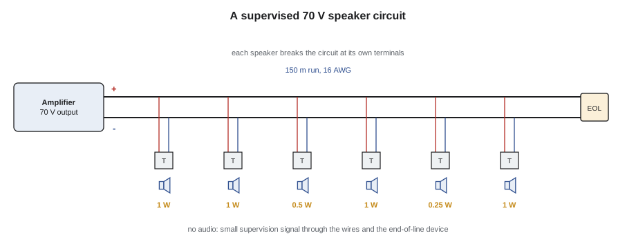
Line loss and wire size
Even a constant-voltage circuit loses some power in the wire. The current flowing through the wire's resistance drops some of the voltage, so the speakers at the far end see a little less than 70 V and produce a little less sound. Designers limit this loss, commonly to about 0.5 to 1 dB, which corresponds to roughly 10 percent of the power. The loss depends on the circuit's load, the voltage and the length and size of the wire. A long circuit with many speakers on small wire can lose far more than intended, which is one reason the design gives a maximum length for each circuit.
# 70 V speaker circuit: line loss for different wire sizes (Riverlight corridor circuit)
import math
V = 70.0
load_w = 60                  # tapped load on the circuit, watts
length = 150                   # one-way length, metres
R_PER = {"18 AWG": 21.0, "16 AWG": 13.2, "14 AWG": 8.28}                    # copper resistance, ohms per km per conductor
I = load_w / V
for gauge, r in R_PER.items():
    loop = 2 * length * r / 1000        # out and back
    v_drop = I * loop
    v_end = V - v_drop
    loss_db = 20 * math.log10(V / v_end)
    flag = "OK" if loss_db <= 0.5 else "too much loss"
print(f"{gauge:>7s}: drop {v_drop:4.2f} V, end voltage {v_end:5.1f} V, loss {loss_db:4.2f} dB {flag}")18 AWG: drop 5.40 V, end voltage 64.6 V, loss 0.70 dB too much loss 16 AWG: drop 3.39 V, end voltage 66.6 V, loss 0.43 dB OK 14 AWG: drop 2.13 V, end voltage 67.9 V, loss 0.27 dB OK
The result shows why Ravi specified 16 AWG for the Riverlight speaker circuits even though the longest run on any floor is short: the same cable type runs from each cabinet to the farthest floor it serves, and on the longest circuits 18 AWG would exceed the loss limit. Wire size is part of the design, and the installer must not substitute a smaller cable because it is easier to pull.
Speaker spacing and coverage
A ceiling speaker spreads its sound in a cone below it. The width of the cone depends on the speaker's dispersion angle, which varies with frequency: wide at low frequencies and narrower at the high frequencies that carry the consonants of speech. The area covered at ear height depends on the ceiling height and the dispersion angle. In a corridor or an open area, speakers are spaced so that their coverage areas meet or overlap at ear height, so that a listener walking along never passes through a dead spot between them.
Close spacing with low taps generally gives clearer speech than wide spacing with high taps. With many speakers each at a low level, every listener is close to a speaker and hears mostly direct sound, which is clear; with few speakers at high levels, listeners far from a speaker hear more reflected sound, which blurs speech. That is the main reason voice systems have more speakers than tone systems: a horn can be heard through a closed door, but a voice message heard through a door is often impossible to understand.
# Ceiling speaker spacing from ceiling height and dispersion angle
import math
ceiling = 2.7        # ceiling height, m
ear = 1.5            # listener ear height (seated or standing), m
angle = 120          # rated dispersion angle at 2 kHz, degrees
d = ceiling - ear
radius = d * math.tan(math.radians(angle / 2))
print(f"Coverage radius at ear height: {radius:.2f} m")
for name, spacing in (("edge to edge", 2 * radius), ("minimum overlap", 1.41 * radius), ("one radius", radius)):
    print(f"{name:16s} spacing: {spacing:.2f} m")
corridor = 24       # corridor length, m
for name, k in (("edge-to-edge", 2.0), ("minimum-overlap", 1.41)):
    n = math.ceil(corridor / (k * radius))
print(f"Speakers for a {corridor} m corridor at {name} spacing: {n}")Coverage radius at ear height: 2.08 m edge to edge spacing: 4.16 m minimum overlap spacing: 2.93 m one radius spacing: 2.08 m Speakers for a 24 m corridor at edge-to-edge spacing: 6 Speakers for a 24 m corridor at minimum-overlap spacing: 9
The calculation gives six speakers for a Riverlight corridor at edge-to-edge spacing, which matches the six corridor speakers on each floor in Ravi's design, and nine at minimum-overlap spacing. Ravi chose edge-to-edge spacing for the corridors because people pass through them rather than stay, and because the corridors are carpeted and quiet; he used closer spacing in the ground floor lobby, which is hard-surfaced and busier. In practice the layout also has to avoid the light fixtures and sprinkler heads, and speakers near the ends of the corridor are placed to cover the doors to the stairs and the elevator lobby.
Phasing, polarity and termination
Every speaker has a positive and a negative terminal, and every speaker on a circuit must be connected the same way round. If one speaker is reversed, its cone moves inward while its neighbours move outward, and where their sound overlaps, the two partly cancel, especially at low frequencies. The result is a thin, hollow sound in the overlap zone and less overall level. A reversed speaker doesn't cause a trouble signal and can easily be missed, so the termination procedure is strict: the same conductor colour to the same terminal on every speaker, checked by a second person or with a polarity tester before the ceiling is closed.
Speaker circuits are terminated in the same way as other notification circuits: the conductors are not looped under one terminal screw, but are broken at each speaker so that removing a speaker opens the circuit and causes a trouble, which the standards require for supervision. Wire nuts are not used on the speaker leads where the maker's instructions require terminal connections. At the end of the circuit, the end-of-line device lets the amplifier supervise the line for opens and shorts.
Supervision of speaker circuits
When no audio is playing, the amplifier or the control unit supervises each speaker circuit by passing a small DC current or an inaudible tone through it and watching for a change. The speaker transformers block DC, so the supervision current flows only through the wires and the end-of-line device, and an open or short in the wiring is detected. During an alarm, when the circuit is playing audio, many systems continue to supervise for shorts. A ground fault is detected in the usual way.
Supervision checks the wiring, not the speakers. A speaker whose cone is torn, whose tap is wrong, or whose connections are reversed will not cause a trouble signal. That is why every speaker must be listened to during testing, and why speaker taps and polarity are checked during installation rather than left for the final test.
Worked problem
Finding a quiet speaker on the 11th floor
During pre-testing, Sasha walks the 11th-floor corridor with the test message playing. Five speakers sound normal, but the sound near the sixth, by the elevator lobby, is thin and noticeably quieter. There is no trouble at the panel. What should she check?
Show solution
- Check the tap setting on the quiet speaker against the design schedule: the schedule says 1 W, and it is found on 0.25 W.
- Check the polarity: compare the terminal connections with the neighbouring speakers.
- Check the speaker itself: listen for rattles or distortion that suggest a damaged cone.
- Correct the tap and confirm the polarity, then listen again along the whole corridor.
- Record the correction on the tap schedule.
Answer: The speaker was tapped at 0.25 W instead of 1 W, about 6 dB too quiet. Once corrected, the corridor sounds even along its length. A trouble signal would never have found it.
Speakers in special locations
Some locations need special speakers. Outdoors, in parking structures and in wet areas, speakers must be listed for the environment, usually with weatherproof enclosures and back boxes. In high-noise spaces such as mechanical rooms, horn-type speakers deliver more level, though often less clarity. In psychiatric units and detention areas, speakers are tamper-resistant and fixed with security screws. And in suites, where the speaker must wake a sleeping resident, the bedroom speaker's tap and location are chosen to reach the required level at the pillow with the door closed, which lesson 11 shows how to measure.
Common mistakes
MistakeSetting taps by ear instead of from the schedule.
InsteadSet every tap to the design and record it.
MistakeReversing a speaker's polarity.
InsteadUse the same conductor to the same terminal on every speaker, and check.
MistakeLooping conductors under one terminal.
InsteadBreak the circuit at each speaker so removal is supervised.
MistakeSubstituting smaller wire on a long speaker circuit.
InsteadUse the designed wire size; line loss depends on it.
MistakeRelying on supervision to find bad speakers.
InsteadSupervision checks the wiring; listen to every speaker.
Summary and key terms
- Fire alarm speakers are listed appliances with transformer taps that set their power.
- Doubling the tap power raises the sound level by about 3 dB.
- Constant-voltage circuits at 25 V or 70 V let each speaker's power depend only on its tap.
- Line loss is limited by the design's wire size and circuit length.
- Close spacing at low taps gives clearer speech than wide spacing at high taps.
- Polarity, taps and termination are checked during installation, because supervision won't find them.
- Tap
- A connection on a speaker transformer that sets its power.
- Constant-voltage circuit
- A speaker circuit driven at a fixed nominal voltage such as 25 V or 70 V.
- Sensitivity
- The sound level a speaker produces at a set distance and power.
- Line loss
- Power lost in the circuit wiring, usually expressed in decibels.
- Dispersion angle
- The angle over which a speaker spreads its sound.
- Polarity
- The direction in which a speaker is connected.
Practice problems
Work each problem on paper first, then reveal the answer to check.
How much louder is a speaker on its 2 W tap than on its 0.5 W tap?
Show answer
About 6 dB.
Why do constant-voltage circuits make amplifier sizing simple?
Show answer
The load is the sum of the taps.
What line loss do designers commonly allow?
Show answer
About 0.5 to 1 dB.
What happens where two speakers of opposite polarity overlap?
Show answer
Their sound partly cancels, giving a thin, quieter sound.
Why must every speaker be listened to during testing?
Show answer
Supervision checks the wiring, not the speakers' sound.
Lesson quiz · 5 questions
Score 60% or more to complete this lesson.
Create a free account to save your progress, take quizzes and earn a certificate.