
ELEC-430 · Lesson 8 of 12 · 24 min
Motors, transformers and control circuits
Motor and transformer questions combine table lookups, multipliers and protection rules, and they carry a large share of the marks on most exams. A motor branch circuit has several parts, each sized by a different rule: the conductors, the short-circuit and ground-fault protection, the overload protection, the controller and the disconnecting means. Transformers have their own rules for primary and secondary protection and conductors, and control circuits for both have rules for protection and wiring. This lesson reviews the structure of a motor circuit, motor full-load current tables, conductor sizing, overcurrent and overload protection with worked examples, disconnecting means, multiple motors on a feeder, control circuits, and transformer protection.
The parts of a motor circuit
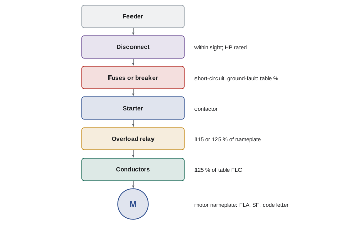
A typical motor branch circuit, from the supply to the motor, contains:
- A disconnecting means, which isolates the motor and controller for maintenance.
- Branch-circuit short-circuit and ground-fault protection, usually fuses or an inverse-time breaker, which protects the conductors and equipment from short circuits and ground faults but is deliberately sized large enough to let the motor start.
- A controller, such as a magnetic starter or variable frequency drive, which starts and stops the motor.
- Overload protection, usually an overload relay in the starter or a function of the drive, which protects the motor and conductors against sustained overcurrent from overloading or failure to start.
- Branch-circuit conductors, sized for the motor's full-load current.
Unlike most circuits, a motor circuit separates short-circuit protection from overload protection, because a motor draws six to eight times its full-load current while starting. A breaker sized close to running current would trip every start; a breaker sized for starting would not protect against overloads. The two functions are therefore provided by different devices with different settings.
Full-load current: table or nameplate?
For most sizing, the CEC requires the full-load current of the motor from the code tables rather than the nameplate: Table 44 for three-phase AC motors and Table 45 for single-phase AC motors, by horsepower and voltage. Tables give typical values for standard motors so that circuits are sized consistently even if the motor is later replaced. The nameplate current is used for overload protection, which must match the actual motor. For example, a 10 hp, 575 V three-phase motor has a table full-load current of 11 A.
Conductors
Branch-circuit conductors for a single motor in continuous duty must have an ampacity of at least 125 % of the motor's table full-load current. The extra 25 % allows for operation slightly above rated current and for the motor's service factor. Conductors supplying several motors are sized at 125 % of the largest motor's full-load current plus 100 % of the others, plus any other loads. Motors with intermittent or short-time duty, such as some cranes and hoists, have different multipliers. Conductors between a drive and its motor, and conductors supplying a drive, follow additional rules based on the drive's rated input current.
Short-circuit and ground-fault protection
Table 29 gives the maximum rating or setting of branch-circuit overcurrent devices as a percentage of the motor full-load current, by motor type and device type. For typical squirrel-cage motors, the percentages are 300 % for non-time-delay fuses, 175 % for time-delay fuses and 250 % for inverse-time circuit breakers. Where the calculated value does not correspond to a standard rating, the next higher standard rating is generally permitted, and further increases are allowed where the motor will not start, within the limits of Section 28.
Overload protection
Rule 28-306 requires overload protection rated or set at no more than 125 % of the full-load current rating of the motor (its nameplate value) for motors with a service factor of 1.15 or more or a marked temperature rise of 40 °C or less, and no more than 115 % for other motors, with higher settings permitted where the motor will not start or carry its load. Thermal protectors integral to small motors may serve as overload protection when approved for the purpose.
Worked problem
A complete motor branch circuit
A 10 hp, 575 V, three-phase squirrel-cage motor has a nameplate full-load current of 10.5 A and a service factor of 1.15. It is protected by an inverse-time breaker. Find the minimum conductor ampacity, the maximum breaker rating and the maximum overload setting.
Show solution
- Table full-load current (Table 44): 11 A.
- Conductors: 1.25 × 11 = 13.75 A minimum ampacity; 14 AWG copper is sufficient.
- Breaker (Table 29, inverse-time, 250 %): 2.5 × 11 = 27.5 A; next higher standard rating: 30 A.
- Overloads (Rule 28-306, service factor 1.15): 1.25 × 10.5 A (nameplate) = 13.1 A maximum.
Answer: Conductors of at least 13.75 A ampacity, a breaker of up to 30 A, and overloads set at no more than 13.1 A.
Notice that the breaker is far larger than the conductor ampacity would normally permit. This is allowed for motor circuits because the overload relay protects the conductors against overload, and the breaker only needs to clear short circuits and ground faults.
Disconnecting means
Each motor and its controller need a disconnecting means that opens all ungrounded conductors and is rated for the motor, usually in horsepower or at least 115 % of the full-load current. The disconnect must generally be within sight of the motor and controller, or capable of being locked in the open position, so that a person working on the motor can be sure it will not be energized. "Within sight" usually means visible and not more than about 15 m (50 ft) away. Exam questions test the rating, location and the conditions under which one disconnect may serve several motors.
Several motors on a feeder
A feeder supplying several motors has conductors rated at least 125 % of the largest motor's full-load current plus the sum of the others' full-load currents, plus other loads. The feeder overcurrent device is sized from the largest branch-circuit protective device rating plus the full-load currents of the other motors, so that the feeder device does not trip when the largest motor starts while the others are running. For example, with motors of 14, 11 and 7.6 A table current and a largest branch breaker of 35 A, the feeder breaker may be rated up to 35 + 11 + 7.6 = 53.6 A, so the next lower standard rating, 50 A, is used for the feeder, as codes generally require rounding down here.
| Item | Sizing basis | Typical multiplier |
|---|---|---|
| Branch conductors, single motor | Table full-load current | 125 % |
| Short-circuit protection, inverse-time breaker | Table full-load current | Up to 250 % |
| Short-circuit protection, time-delay fuse | Table full-load current | Up to 175 % |
| Overload, SF ≥ 1.15 or rise ≤ 40 °C | Nameplate current | Up to 125 % |
| Overload, other motors | Nameplate current | Up to 115 % |
| Feeder conductors, several motors | Table currents | 125 % of largest + 100 % of others |
| Disconnect rating | Motor rating | Horsepower rated or ≥ 115 % FLC |
Control circuits
Motor control circuits, typically at 120 V from a control transformer or tapped from the power circuit, operate starter coils, pilot lights and interlocks. Their conductors are small, often 14 or 16 AWG, and must be protected according to rules that depend on whether the control circuit is tapped from the motor branch circuit and whether the conductors stay within the starter enclosure. A control transformer's secondary is protected by a fuse sized for the transformer, and the circuit is arranged so that a ground fault cannot start the motor: the grounded side of the control transformer goes to the coil, and the switching devices are in the ungrounded side. The standard three-wire start–stop circuit uses a normally open start button with a holding contact in parallel and a normally closed stop button in series, so that the motor does not restart by itself after a power failure, a feature called low-voltage protection.
Variable frequency drives
Variable frequency drives (VFDs) control motor speed by converting the supply to DC and inverting it to variable frequency and voltage. They provide soft starting, so the motor does not draw high starting current, and typically include electronic overload protection programmed with the motor nameplate data. Drive circuits have their own code rules: conductors supplying a drive are sized from the drive's rated input current, the drive manufacturer specifies the branch-circuit protection, and output conductors to the motor may need special cable, bonding and length limits because fast-switching output can cause reflected-wave voltage spikes and bearing currents.
Transformers
A transformer's rated currents follow from its kVA rating and voltages. For three-phase transformers:
For example, a 75 kVA, 600 V to 120/208 V transformer has a primary current of 75,000 / (1.732 × 600) = 72.2 A and a secondary current of 75,000 / (1.732 × 208) = 208 A. Rules 26-250 to 26-258 govern transformer installations: the primary overcurrent device is limited to a percentage of rated primary current, a larger percentage is allowed where secondary protection is also provided, primary and secondary conductors must be sized for at least 125 % of rated current, and the secondary is treated as a separately derived system for grounding (Lesson 6). Check the exact percentages in the rules of your edition.
Transformers also need ventilation and working space, must be accessible, and dry-type transformers above certain ratings have restrictions on installation near combustible materials. Exam questions may ask for currents, protection, conductor sizes or the grounding of a transformer secondary.
Motor nameplates
Nameplate data drive many decisions. A motor nameplate typically lists horsepower or kilowatts, voltage, full-load current, frequency, phase, speed, service factor, insulation class, temperature rise or ambient rating, duty rating, design letter, code letter for locked-rotor kVA per horsepower, efficiency and frame size. Code letters allow the locked-rotor current to be estimated, which matters for sizing disconnects and starting methods. Design letters, such as Design B for typical industrial motors, indicate the torque and current characteristics, and some energy-efficient designs have higher starting currents, which is why codes allow higher instantaneous-trip settings for them.
Hermetic refrigerant motor-compressors
Air-conditioning and refrigeration equipment uses hermetic motor-compressors, sealed inside the refrigerant system. Their nameplates give rated-load current and branch-circuit selection current rather than horsepower, and their circuits are sized from these values or from the equipment's marked minimum circuit ampacity and maximum overcurrent protection. Questions about air-conditioning units usually require reading these nameplate values rather than using motor tables.
Motor questions on the exam
Motor questions often chain several steps, and each step has a characteristic trap. Using nameplate current where table current is required, or the reverse, is the most common. Others include forgetting to round up to the next standard device size where permitted, or rounding up where rounding down is required for motor feeders; applying a 125 % overload limit to a motor that only qualifies for 115 %; using a single-phase table for a three-phase motor; and forgetting that motor disconnects must be horsepower-rated or sized for at least 115 % of full-load current. A clean, written sequence of steps, each with its rule reference, avoids these traps and makes checking easy.
Common mistakes
MistakeUsing nameplate current for conductors and short-circuit protection.
InsteadUse code table currents; use nameplate for overloads.
MistakeSizing motor breakers like ordinary branch circuits.
InsteadUse the motor protection table percentages.
MistakeApplying 125 % overloads to all motors.
InsteadUse 115 % unless the service factor or temperature rise qualifies.
MistakeRounding feeder protection up.
InsteadFeeder protection for motor groups generally rounds down.
MistakeUsing line-to-neutral voltage in three-phase current calculations.
InsteadUse √3 × line-to-line voltage.
Summary and key terms
- Motor circuits separate short-circuit protection from overload protection.
- Use table full-load current for conductors and short-circuit protection.
- Branch conductors are sized at 125 % of table full-load current.
- Inverse-time breakers up to 250 %, time-delay fuses up to 175 % for typical motors.
- Overloads up to 125 % or 115 % of nameplate current.
- Disconnects must be in sight or lockable and suitably rated.
- Transformer currents use kVA × 1000 / (√3 × V); protection follows the transformer rules.
- Full-load current
- Motor current at rated load.
- Service factor
- Permissible overload multiplier on a nameplate.
- Overload relay
- Device protecting a motor from sustained overcurrent.
- Short-circuit protection
- Device clearing short circuits and ground faults.
- Controller
- Device that starts and stops a motor.
- Within sight
- Visible and within a short distance.
- Locked-rotor current
- Current drawn by a stalled or starting motor.
- Low-voltage protection
- Prevents automatic restart after power loss.
- VFD
- Variable frequency drive.
- Control transformer
- Transformer supplying control circuits.
Practice problems
Work each problem on paper first, then reveal the answer to check.
Why are motor short-circuit devices larger than conductor ampacity?
Show answer
They must allow starting current; overloads protect conductors.
Table full-load current of a 10 hp, 575 V three-phase motor?
Show answer
11 A.
Minimum conductor ampacity for a motor with 28 A table current?
Show answer
35 A.
Maximum time-delay fuse for 20 A table current?
Show answer
175 % = 35 A.
Maximum overload for 15 A nameplate, SF 1.0, 50 °C rise?
Show answer
115 % = 17.25 A.
Feeder conductors for motors of 20, 14 and 8 A?
Show answer
1.25 × 20 + 14 + 8 = 47 A.
What does "within sight" usually mean?
Show answer
Visible and not more than about 15 m (50 ft).
Why wire the control coil to the grounded side?
Show answer
So a ground fault cannot start the motor.
Secondary current of a 45 kVA 120/208 V transformer?
Show answer
45,000 / (1.732 × 208) ≈ 125 A.
What feature of three-wire control prevents restart after power loss?
Show answer
The holding contact drops out: low-voltage protection.
Lesson quiz · 5 questions
Score 60% or more to complete this lesson.
Create a free account to save your progress, take quizzes and earn a certificate.