
ELEC-430 · Lesson 4 of 12 · 26 min
Branch circuits, feeders, overcurrent protection and voltage drop
Branch circuits and feeders are the backbone of every installation, and questions about them make up a large share of any electrical exam. They test the definitions that distinguish branch circuits from feeders and services, how to size conductors and overcurrent devices for continuous and non-continuous loads, standard device ratings, protection against ground faults and arc faults, receptacle layout rules in dwellings, and voltage drop. This lesson reviews each topic with worked examples in the style of exam questions.
Services, feeders and branch circuits
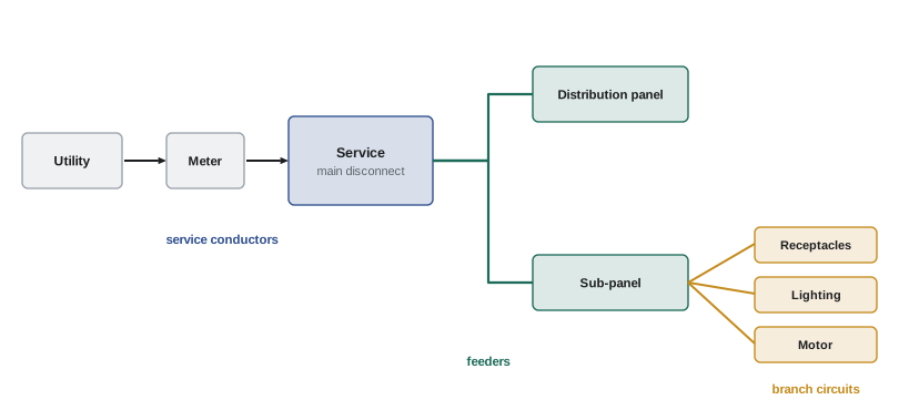
The supply to a building passes through three levels of circuit. The service consists of the conductors and equipment that deliver energy from the utility to the building's wiring system, ending at the service disconnecting means and overcurrent protection. Feeders run from the service equipment, or from a separately derived system such as a transformer, to panelboards and other distribution equipment. Branch circuits run from the final overcurrent device, typically a breaker in a panelboard, to the outlets, such as receptacles, luminaires and appliances. Exam questions frequently depend on recognizing which of these a set of conductors is, because different rules apply to each.
Continuous loads
A continuous load is one where the maximum current is expected to continue for three hours or more, such as store lighting, office lighting, electric heating and many industrial processes. Conductors and overcurrent devices are tested at their ratings under controlled conditions, and in real enclosures continuous operation at full rating can overheat them, so codes require extra capacity for continuous loads.
In the CEC, Rule 8-104 requires that the calculated continuous load not exceed 80 % of the rating of the overcurrent device and the conductor ampacity, or 100 % where the assembly, such as a fused switch or breaker in its enclosure, is marked for continuous operation at 100 % of its rating. Expressed another way, a continuous load requires a device rated at least 125 % of the load. Rule 8-104 also gives the conditions under which a load is considered continuous.
Worked problem
Sizing for a continuous load
A branch circuit supplies 22 A of lighting that operates for 12 hours a day, plus 4 A of non-continuous load. Equipment terminals are rated 75 °C. Find the minimum overcurrent device rating and copper conductor size.
Show solution
- Continuous portion at 125 %: 22 × 1.25 = 27.5 A.
- Add non-continuous load: 27.5 + 4 = 31.5 A.
- Next standard overcurrent device rating: 35 A.
- Conductor: 10 AWG copper has 35 A in the 75 °C column, enough for 31.5 A, but small-conductor rules limit 10 AWG copper to 30 A protection, so it cannot be used with a 35 A device.
- Choose 8 AWG copper (50 A at 75 °C) with a 35 A device.
Answer: A 35 A overcurrent device with 8 AWG copper conductors; 10 AWG is ruled out by the 30 A limit for small conductors.
Standard overcurrent device ratings
Commonly available fuse and breaker ratings include 15, 20, 25, 30, 35, 40, 45, 50, 60, 70, 80, 90, 100, 110, 125, 150, 175, 200, 225, 250, 300, 350, 400, 450, 500, 600 A and upward. Where a conductor's ampacity does not match a standard rating, Rule 14-104 generally permits the next higher standard rating, within the limits and conditions the rule sets; read those conditions carefully, especially for larger feeders.
Overcurrent devices also have an interrupting rating, the maximum fault current they can safely interrupt, which must be at least the available fault current at their location. Exam questions may present a short-circuit current and ask whether a device with a stated interrupting rating is suitable, or ask about series-rated combinations of breakers tested together.
Ground-fault and arc-fault protection
Ground-fault circuit interrupters (GFCIs) protect people from shock by opening the circuit when the current leaving on the line conductor differs from the current returning on the neutral by more than about 5 mA (4 to 6 mA for Class A devices), indicating that current is flowing through an unintended path, possibly a person. They are required in locations where people are likely to contact water or earth. Arc-fault circuit interrupters (AFCIs) detect the electrical signatures of arcing, from damaged cords, loose connections or nails through cables, and open the circuit to prevent fires. Ground-fault protection of equipment (GFPE), set at much higher levels, protects equipment from destructive arcing ground faults on large solidly grounded wye services.
In the CEC, Section 26 sets out where GFCI protection is required, including receptacles near sinks, bathtubs and showers, outdoor receptacles, and receptacles in certain other wet or damp locations, and where AFCI protection is required for branch circuits supplying receptacles in dwelling units, with listed exceptions. Section 68 adds GFCI requirements for pools, hot tubs and spas, and Section 14 covers ground-fault protection of large services. Requirements have expanded in recent editions, so check the edition you will be given.
Receptacle layout in dwellings
Dwelling receptacle rules in Section 26 aim to put a receptacle within reach of a typical cord. In general, receptacles in finished walls are located so that no point along the floor line of any usable wall space is more than 1.8 m horizontally from a receptacle, and kitchen counter receptacles are located so that no point along the wall line of the counter is more than 900 mm from a receptacle. Kitchen counter receptacles are typically supplied by split or individual circuits, and specific rules apply to bathrooms, laundry areas, outdoor receptacles and receptacles for appliances. Tamper-resistant receptacles are required in dwelling units.
Voltage drop
Long circuits lose voltage along their conductors, reducing the voltage at the load, which can make motors run hot, lights dim and electronic equipment malfunction. Voltage drop in a two-wire circuit is the current times the resistance of both conductors, the outgoing and the return:
Here \(R\) is the conductor resistance per unit length and \(L\) the one-way length. For AC circuits with large conductors, reactance also matters, and more exact methods use effective impedance. For exam purposes, the resistance method is usually sufficient.
The CEC makes voltage drop mandatory: Rule 8-102 limits the voltage drop to 3 % in a feeder or branch circuit and 5 % overall from the supply side of the consumer's service, or the secondary of a transformer, to the point of use. Appendix D includes Table D3, which gives the distance for a 1 % drop for given currents and conductor sizes, allowing quick answers without calculation.
Worked problem
Sizing for voltage drop
A 120 V, 16 A load is supplied by copper conductors 30 m from the panel. Using resistances of 6.34 Ω/km for 12 AWG, 3.97 Ω/km for 10 AWG and 2.50 Ω/km for 8 AWG, find the smallest size that keeps voltage drop within 3 %.
Show solution
- Allowed drop: 3 % of 120 V = 3.6 V.
- Total conductor length: 2 × 30 m = 60 m = 0.060 km.
- 12 AWG: 16 × 6.34 × 0.060 = 6.09 V (5.1 %), too high.
- 10 AWG: 16 × 3.97 × 0.060 = 3.81 V (3.2 %), slightly too high.
- 8 AWG: 16 × 2.50 × 0.060 = 2.40 V (2.0 %), acceptable.
Answer: 8 AWG copper. Ampacity alone would allow 12 AWG, but voltage drop requires two sizes larger.
Multi-wire branch circuits
A multi-wire branch circuit shares one neutral between two or three ungrounded conductors from different phases, saving a conductor. When loads are balanced, the neutral carries little current. Because opening the neutral of a multi-wire circuit can put loads in series across 240 V and damage equipment, codes require that the neutral not depend on device terminals for continuity, usually by splicing neutrals with pigtails, and that the ungrounded conductors be disconnected simultaneously, typically by a two-pole or handle-tied breaker, where they supply devices on the same yoke or in other specified situations. Multi-wire circuits supplying non-linear loads can overload the shared neutral with harmonic currents.
Feeder sizing and taps
Feeders are sized from the calculated load using the demand factors of the relevant calculation rules (Lesson 5), plus the continuous-load multiplier where it applies. Conductors smaller than the feeder's overcurrent device, called taps, are permitted under specific conditions of length, ampacity and termination, such as short taps to a single overcurrent device. Tap rules are detailed and frequently examined; read every condition. Feeder neutrals are sized for the maximum unbalanced load, with demand factors permitted for some loads but not for non-linear loads or electric discharge lighting.
Branch circuit ratings and receptacles
A branch circuit's rating is set by its overcurrent device, not by its conductors, and the receptacles on it must suit that rating. A 15 A receptacle may be installed on a 20 A circuit where there are two or more receptacles, while a single receptacle on an individual branch circuit must have a rating at least equal to the circuit. Cord-and-plug-connected loads on a circuit are generally limited to a percentage of the circuit rating, and fixed equipment supplied by a circuit that also serves lighting or receptacles is limited in the same way, so that the remaining capacity is available for other loads. Exam questions combine these rules with continuous-load requirements.
Selective coordination and protection
In large systems, overcurrent devices are coordinated so that a fault is cleared by the device nearest to it, leaving the rest of the system in service. Coordination requires comparing time-current curves of upstream and downstream devices. Codes require selective coordination for some critical systems, such as emergency systems, legally required standby systems and elevators. Other protective concepts that appear in questions include current-limiting fuses, which open within the first half cycle of a large fault and limit the energy let through, and series ratings, which allow a downstream breaker with a lower interrupting rating to be protected by an upstream device when the combination has been tested.
Feeder neutrals
Feeder neutral conductors carry the maximum unbalanced load between the neutral and any ungrounded conductor. In a balanced three-phase four-wire system, linear loads produce little neutral current, but codes require the neutral to be sized for the calculated maximum unbalance, with demand factors permitted for some large loads but not for non-linear loads such as electronic equipment and discharge lighting. Where large non-linear loads are present, the neutral may need to be larger than the phase conductors, and it counts as a current-carrying conductor for derating.
Branch circuits for specific loads
Some loads require dedicated or specifically sized branch circuits: fixed space heating, which is usually treated as continuous; water heaters, which some codes require to be treated as continuous; central heating equipment, which typically needs an individual circuit; laundry equipment; and kitchen appliances such as dishwashers, ranges and built-in microwave ovens. Questions may ask for the minimum circuit rating for a specific appliance, combining the appliance nameplate with continuous-load rules and the next standard device rating.
Common mistakes
MistakeSizing for continuous loads at 100 %.
InsteadUse 125 % of continuous load (or 80 % of device rating).
MistakeForgetting small-conductor limits after rounding up a device.
InsteadCheck that the conductor may be protected at that rating.
MistakeConfusing feeders and branch circuits.
InsteadIdentify the circuit level from where it starts and ends.
MistakeUsing one-way length in voltage drop for two-wire circuits.
InsteadUse twice the one-way length (or √3 for three phase).
MistakeAssuming interrupting rating equals ampere rating.
InsteadCheck interrupting rating against available fault current.
Summary and key terms
- Service, feeder and branch circuit are distinct levels with different rules.
- Continuous loads need 125 % capacity unless equipment is rated 100 %.
- Use standard device ratings and the next-higher-rating rule with care.
- Interrupting ratings must meet available fault current.
- GFCIs protect people; AFCIs reduce fire risk; GFPE protects large services.
- Dwelling receptacle spacing keeps outlets within cord reach.
- Voltage drop is 2IRL (single phase) or √3IRL (three phase).
- Service
- Conductors and equipment delivering supply to the building.
- Feeder
- Circuit between service equipment and final overcurrent device.
- Branch circuit
- Circuit from final overcurrent device to outlets.
- Continuous load
- Maximum current lasting three hours or more.
- Interrupting rating
- Maximum fault current a device can interrupt.
- GFCI
- Device opening on small line-to-ground leakage.
- AFCI
- Device opening on detected arcing.
- GFPE
- Ground-fault protection of equipment.
- Multi-wire branch circuit
- Circuit sharing one neutral among phases.
- Tap
- Smaller conductor connected to a larger feeder.
Practice problems
Work each problem on paper first, then reveal the answer to check.
Minimum device for 40 A continuous load?
Show answer
50 A (40 × 1.25).
Minimum device for 16 A continuous plus 6 A non-continuous?
Show answer
26 A → 30 A.
What standard rating follows 110 A?
Show answer
125 A.
At what leakage does a GFCI trip?
Show answer
About 5 mA (4–6 mA).
What does an AFCI protect against?
Show answer
Fires from arcing faults.
Maximum distance along a floor line to a receptacle?
Show answer
1.8 m.
Allowed 3 % drop on 208 V?
Show answer
6.24 V.
Voltage drop for 20 A over 25 m of 10 AWG copper (3.97 Ω/km), single phase?
Show answer
2 × 20 × 3.97 × 0.025 = 3.97 V.
Why must a multi-wire neutral not depend on device terminals?
Show answer
An open neutral can put loads in series across 240 V.
What must interrupting rating be compared with?
Show answer
Available fault current.
Lesson quiz · 5 questions
Score 60% or more to complete this lesson.
Create a free account to save your progress, take quizzes and earn a certificate.