
ELEC-430 · Lesson 6 of 12 · 25 min
Services, grounding and bonding
Grounding and bonding is one of the most heavily examined subjects in the trade and one of the most misunderstood. The vocabulary is precise, the purposes of grounding and bonding are different, and the rules for services, feeders, separately derived systems and special locations differ in important details. Services themselves bring their own rules on the number of services, clearances, disconnecting means and equipment. This lesson reviews service equipment, the purposes of system grounding and equipment bonding, the neutral-to-ground connection, grounding electrodes and their conductors, sizing bonding conductors, bonding of piping and structural metal, separately derived systems and common errors that cause shock and fire hazards.
The service
Section 6 of the CEC governs the consumer's service: the conductors and equipment from the supply authority's point of connection to the service box or equivalent. In general, a building is supplied by one consumer's service, with exceptions for large buildings, different voltages or classes of service, and fire pumps and emergency supplies. Service equipment must be readily accessible, located as close as practicable to the point where conductors enter the building, and include a means of disconnecting all ungrounded conductors and overcurrent protection. Supply authorities have their own requirements for meters, service masts, clearances and the point of connection, which work together with the code; on the job, both must be followed.
Grounding versus bonding
Two different ideas sit under this heading, and many errors come from mixing them up.
- System grounding connects one conductor of the supply system, usually the neutral, to earth. It limits the voltage to ground caused by lightning, utility surges and accidental contact with higher-voltage lines, and stabilizes the voltage to ground during normal operation.
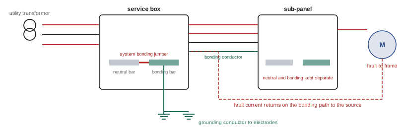
- Equipment bonding connects the non-current-carrying metal parts of the installation, such as enclosures, raceways, equipment frames and metal piping, to each other and to the grounded system conductor at the service. It creates a low-impedance fault path, so that if a live conductor touches metal, enough current flows to operate the overcurrent device quickly, and it keeps metal parts at nearly the same potential so people are not exposed to dangerous touch voltages.
The earth itself is a poor conductor. A fault from a live conductor to a ground rod, with no metallic return path, may draw only a few amperes, far too little to trip a breaker, while raising the metal to a dangerous voltage. The metallic fault path through bonding conductors, not the earth, is what clears faults.
The CEC uses "grounding" for the connection to earth through the grounding electrode and grounding conductor, and "bonding" for the connection of non-current-carrying metal parts and the bonding conductor that runs with circuit conductors. Section 10 was extensively reorganized in the 2021 edition, so make sure your practice questions match the edition you will write.
The neutral-to-ground connection
At the service, the grounded neutral is connected to the bonding system and grounding electrode through a main or system bonding jumper. Downstream of the service, in sub-panels and equipment, the neutral must be insulated from the enclosure and the bonding conductors. If the neutral and ground are connected at a sub-panel as well, normal neutral current divides between the neutral and the bonding conductors, raceways and metal piping, creating "objectionable current" on metal parts, magnetic fields, interference with electronic equipment and, if the neutral opens, energized enclosures. Exam questions frequently test where the neutral-to-ground bond belongs and the separation required in sub-panels and in detached buildings supplied by feeders.
Grounding electrodes
Grounding electrodes connect the system to earth. The CEC recognizes manufactured and field-assembled electrodes, including concrete-encased electrodes in footings, ground plates, rod electrodes and buried conductors, and in-situ electrodes such as metal water piping systems where permitted. Field-assembled rod electrodes generally consist of rods at least 3 m long, with two rods spaced at least 3 m apart unless conditions in the rule allow otherwise, driven to their full length or laid in trenches where rock prevents driving. The grounding conductor connects the system at the service to the electrode, sized from Table 17 according to the ampacity of the largest service conductor, and must be continuous, protected from damage and connected with listed means.
| Item | Typical CEC requirement |
|---|---|
| Grounding conductor size | Table 17, based on service conductor ampacity |
| Bonding conductor size | Table 16, based on the rating of the overcurrent device or conductor ampacity |
| Rod electrodes | Usually two rods, at least 3 m long and 3 m apart |
| System bonding | At the service; neutral isolated downstream |
| Metal water piping | Bonded to the grounding system |
| Detached buildings fed by feeder | Separate bonding conductor; neutral isolated |
Sizing bonding conductors
Bonding conductors that run with circuit conductors are sized from Table 16, based on the rating or setting of the overcurrent device protecting the circuit, or in some cases the ampacity of the largest ungrounded conductor. The bonding conductor need not be larger than the largest ungrounded conductor. For example, a feeder protected at 200 A requires a 6 AWG copper bonding conductor. Where circuit conductors are increased in size for voltage drop, the bonding conductor must be increased proportionally in some situations, and metal raceways and the armour of some cables can serve as the bonding means where the code permits.
Worked problem
Sizing grounding and bonding conductors
A dwelling service uses 3/0 AWG copper service conductors rated 200 A. A detached garage is fed by a feeder protected at 60 A. Find the grounding conductor size for the service and the bonding conductor size for the garage feeder.
Show solution
- Service grounding conductor: look up Table 17 for the ampacity of the largest service conductor (200 A) in your edition; for this size the table gives 6 AWG copper.
- Garage feeder bonding conductor: Table 16 for a 60 A overcurrent device gives 10 AWG copper.
- At the garage, the neutral is isolated from the enclosure and the bonding conductor is connected to the enclosure, with a grounding electrode at the garage where required.
Answer: A 6 AWG copper grounding conductor for the service (check Table 17 in your edition) and a 10 AWG copper bonding conductor for the 60 A garage feeder.
Bonding piping, structural metal and other systems
Metal piping systems that may become energized, such as water piping, gas piping and sprinkler piping, must be bonded to the grounding system so that a fault to the piping operates protection and does not create a shock hazard. The bonding conductor size and connection point depend on the code and the type of piping. Structural steel that may become energized is also bonded. Communication systems, such as telephone, cable television and antennas, must be bonded to the same grounding system as the power, so that a lightning surge does not create a large voltage between systems inside the building; codes require an accessible means for making this intersystem bonding connection near the service.
Separately derived systems
A separately derived system is a source with no direct electrical connection to the supply conductors of another system, apart from grounding and bonding connections, such as a transformer with separate primary and secondary windings, a generator with a switched neutral, or a solar inverter in some configurations. Because its secondary is isolated, it needs its own system grounding: a system bonding jumper connecting the derived neutral to the bonding system at one point, either at the source or at the first disconnecting means, and a grounding conductor to a grounding electrode. Questions often ask where to put the bonding jumper, what size it must be and which electrode to use for a building transformer supplying a 120/208 V panel.
Ungrounded and impedance-grounded systems
Not every system is solidly grounded. Ungrounded systems, still used in some industrial plants, continue operating after a first ground fault, which can be valuable where unplanned shutdowns are dangerous or costly, but they need ground detection so that the first fault is found and repaired before a second fault on another phase causes a short circuit. High-resistance grounded systems connect the neutral to ground through a resistor that limits ground-fault current to a few amperes, allowing continued operation with an alarm and avoiding the high transient overvoltages of ungrounded systems. These systems have their own code rules for detection, marking and the loads that may be connected, and appear in industrial exam questions.
Common grounding and bonding errors
- Bonding neutral to ground in sub-panels, creating parallel neutral paths.
- Relying on a ground rod as the fault return path.
- Missing or loose bonding jumpers around water meters, flexible connections or concentric knockouts.
- Undersized bonding conductors where circuit conductors were upsized.
- Painted surfaces under bonding connections.
- Using a neutral as an equipment bonding conductor downstream of the service.
Each of these can leave metal parts energized during a fault or allow current on paths not designed for it. Inspectors and exams both focus on them.
Bonding at the service
At the service, bonding receives special attention because the service conductors are protected only by the utility's overcurrent devices, which may not open quickly for a fault on the line side of the main disconnect. Service raceways and enclosures must therefore be bonded by methods that ensure continuity under high fault currents: threaded connections, bonding jumpers around concentric or eccentric knockouts, bonding bushings and locknuts that cut through paint. Service bonding jumpers are sized from the size of the service conductors rather than an overcurrent device rating.
Bonding flexible and isolated sections
Flexible conduit, expansion joints, non-metallic sections of piping and other discontinuities can break the bonding path. Bonding jumpers are installed around them, sized for the circuit, and kept short. Metal water meters and water heaters with dielectric fittings are common places where bonding jumpers are needed to keep metal water piping continuous. Where equipment is mounted on vibration isolators, flexible bonding jumpers maintain the connection. Questions may describe a piping system or a motor on isolation mounts and ask what bonding is required.
Testing grounding and bonding
Grounding and bonding are tested during commissioning and maintenance. Continuity tests with a low-resistance ohmmeter confirm that bonding paths are complete. Ground resistance tests, such as the fall-of-potential method, measure the resistance of electrodes to earth. Ground-fault loop impedance measurements show whether a fault would draw enough current to trip the overcurrent device quickly. Exam questions on testing link this lesson with troubleshooting topics.
Grounding and bonding for generators and inverters
Portable and standby generators raise grounding questions that appear on exams. Whether a generator is a separately derived system depends on whether its neutral is switched by the transfer switch: if the neutral is solidly connected through the transfer switch to the service neutral, the generator is not separately derived and must not have its own neutral-to-ground bond, because that would create a parallel neutral path; if the transfer switch switches the neutral, the generator is separately derived and needs its own system bonding and grounding. Inverters for solar and battery systems have similar considerations, and their manufacturers' instructions state how they must be grounded. Getting this wrong creates either objectionable current or an ungrounded system, both of which inspectors and exam writers look for.
Common mistakes
MistakeThinking the earth clears faults.
InsteadThe metallic bonding path returns fault current to the source.
MistakeBonding neutral to ground at a sub-panel.
InsteadBond only at the service or separately derived source.
MistakeSizing bonding conductors from load current.
InsteadSize from the overcurrent device rating table.
MistakeForgetting to supplement or bond electrodes.
InsteadBond all electrodes present and supplement as required.
MistakeForgetting system grounding for transformers.
InsteadTreat transformer secondaries as separately derived systems.
Summary and key terms
- Generally one service per building, with listed exceptions.
- System grounding limits voltage to ground; bonding provides the fault path.
- The earth is not an effective fault return path.
- Neutral and ground are bonded only at the service or derived source.
- Electrodes are bonded together; rods have length, spacing and supplementing rules.
- Grounding conductors are sized from service conductors; bonding conductors from overcurrent ratings.
- Separately derived systems need their own bonding jumper and electrode.
- Service
- Conductors and equipment from supply to premises wiring.
- System grounding
- Connecting a supply conductor to earth.
- Equipment bonding
- Connecting metal parts to form a fault path.
- Grounding electrode
- Conductive object connecting to earth.
- Grounding conductor
- Conductor from the system to the electrode.
- Bonding conductor
- Conductor bonding equipment, run with circuit conductors.
- System bonding jumper
- Connection between neutral and bonding system.
- Objectionable current
- Neutral current on bonding paths.
- Separately derived system
- Source with no direct connection to another system.
- High-resistance grounding
- Neutral grounded through a resistor.
Practice problems
Work each problem on paper first, then reveal the answer to check.
What does equipment bonding provide?
Show answer
A low-impedance fault path and equal potential.
Why can a ground rod alone not clear a fault?
Show answer
Earth resistance limits current below breaker trip levels.
Where is the neutral bonded to ground?
Show answer
At the service or separately derived source only.
What happens if neutral and ground are bonded in a sub-panel?
Show answer
Neutral current flows on bonding paths.
Typical rod electrode requirement?
Show answer
Two rods at least 3 m long, 3 m apart.
Which table sizes bonding conductors?
Show answer
Table 16.
Which table sizes the service grounding conductor?
Show answer
Table 17.
Why bond communication systems to the power grounding system?
Show answer
To avoid voltage differences between systems during surges.
Give an example of a separately derived system.
Show answer
A building transformer with isolated secondary.
Why use high-resistance grounding?
Show answer
Continue operating after a first fault while limiting overvoltages.
Lesson quiz · 5 questions
Score 60% or more to complete this lesson.
Create a free account to save your progress, take quizzes and earn a certificate.