
ELEC-430 · Lesson 3 of 12 · 24 min
Conductors, ampacity and derating
Conductor sizing questions appear throughout electrical exams, on their own and as steps inside larger problems on feeders, services and motors. The basic idea is simple: a conductor must carry its load without overheating its insulation. In practice, the answer depends on the conductor material, insulation temperature rating, installation method, ambient temperature, the number of current-carrying conductors grouped together, and the temperature ratings of the terminations at each end. Exam questions test whether you apply all of these in the right order. This lesson reviews conductor types and markings, the ampacity tables, ambient temperature correction, adjustment for grouped conductors, which conductors count as current-carrying, termination limits, aluminum conductors and small-conductor protection limits.
Why ampacity is limited
Current through a conductor produces heat in proportion to the square of the current times the resistance (\(I^2R\)). The conductor's temperature rises until heat escapes to the surroundings as fast as it is produced. Insulation has a maximum continuous operating temperature, commonly 60, 75 or 90 °C, above which it ages rapidly, becomes brittle and eventually fails. Ampacity is the current a conductor can carry continuously under stated conditions without exceeding its insulation's temperature rating. Anything that makes it harder for heat to escape, such as a hot room, many conductors bundled together, thermal insulation or a buried location, reduces ampacity.
Conductor types and markings
Common building wire types in Canada include RW90 and RWU90 (cross-linked polyethylene insulation, rated 90 °C, the latter for underground use), T90 Nylon (thermoplastic with nylon jacket, 90 °C dry), TWN75 and TWU75, and NMD90 non-metallic sheathed cable used in dwellings. Armoured cables include AC90 (BX) and ACWU90, and teck cable (TECK90) is widely used in industrial installations. Table 19 lists conductor types, their insulation, temperature ratings and permitted uses. The temperature rating in the name, such as 90 in RW90, tells you which ampacity column the conductor may use as a starting point.
The ampacity tables
For copper conductors, Table 1 gives ampacities for single conductors in free air and Table 2 for not more than three conductors in a raceway or cable, or directly buried; Tables 3 and 4 give the same for aluminum. Each table has columns for 60 °C, 75 °C and 90 °C insulation and assumes an ambient temperature of 30 °C. Rule 4-004 explains how the tables are applied, including conditions for underground installations, which use Tables D8A to D11B and the calculation methods of Appendix D, and for cables in contact with thermal insulation.
| Copper size (AWG/kcmil) | 60 °C | 75 °C | 90 °C |
|---|---|---|---|
| 14 | 15 | 20 | 25 |
| 12 | 20 | 25 | 30 |
| 10 | 30 | 35 | 40 |
| 8 | 40 | 50 | 55 |
| 6 | 55 | 65 | 75 |
| 4 | 70 | 85 | 95 |
| 3 | 85 | 100 | 115 |
| 2 | 95 | 115 | 130 |
| 1 | 110 | 130 | 145 |
| 1/0 | 125 | 150 | 170 |
| 2/0 | 145 | 175 | 195 |
| 3/0 | 165 | 200 | 225 |
| 4/0 | 195 | 230 | 260 |
Ambient temperature correction
Where the ambient temperature differs from the 30 °C basis of the tables, the table ampacity is multiplied by a correction factor. Higher ambient temperatures reduce ampacity because the conductor has less temperature margin before reaching its rating. The factor depends on both the ambient temperature and the conductor's insulation rating; 90 °C conductors lose a smaller fraction of their ampacity in hot locations than 60 °C conductors.
In the CEC, correction factors for ambient temperatures other than 30 °C are given in Table 5A. For example, at 40 °C the factor is 0.91 for 90 °C insulation and 0.88 for 75 °C insulation.
Adjustment for more than three conductors
When more than three current-carrying conductors share a raceway or cable, or are bundled together over a significant length, each conductor's heat makes it harder for its neighbours to cool, so ampacity is reduced further.
| Number of current-carrying conductors | Correction factor (CEC Table 5C) |
|---|---|
| 1 to 3 | 1.00 |
| 4 to 6 | 0.80 |
| 7 to 24 | 0.70 |
| 25 to 42 | 0.60 |
| 43 and more | 0.50 |
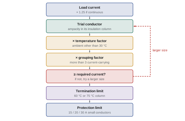
Both correction and adjustment factors, when they apply, are multiplied together with the table ampacity. They are usually applied to the ampacity in the conductor's own insulation column, for example the 90 °C column for a 90 °C conductor, and the result must then also satisfy the termination limit described below.
Which conductors count
Not every conductor in a raceway counts as current-carrying for adjustment purposes. Equipment bonding or grounding conductors never count. A neutral that carries only the unbalanced current of the circuits it serves, such as the neutral of a three-wire single-phase circuit or a four-wire three-phase wye circuit supplying linear loads, generally does not count, because the phase currents largely cancel. A neutral does count when it carries significant current that does not cancel: for example, the neutral of a two-wire circuit, the neutral of a circuit with two phases and the neutral of a three-phase wye system, and a neutral serving mainly non-linear loads such as electronic equipment and LED drivers, whose triplen harmonic currents add in the neutral. Control and signal conductors carrying negligible current may be excluded where the code allows. Counting correctly is a frequent exam trap.
Worked problem
Derating for temperature and grouping
Six current-carrying 10 AWG copper RW90 conductors run in one conduit through a space at 40 °C and terminate on equipment rated 75 °C. What is the allowable ampacity of each conductor?
Show solution
- Start in the 90 °C column of Table 2: 10 AWG copper = 40 A.
- Ambient correction, Table 5A, 90 °C insulation at 40 °C: 0.91.
- Grouping correction, Table 5C, 4 to 6 conductors: 0.80.
- Derated ampacity: 40 × 0.91 × 0.80 = 29.1 A.
- Termination limit: 75 °C column for 10 AWG = 35 A. The derated value, 29.1 A, is lower, so it governs.
Answer: About 29 A. Overcurrent protection rules for small conductors then limit the protective device on 10 AWG copper to 30 A.
Termination temperature limits
Rule 4-006 recognizes that the ends of a conductor are connected to equipment, such as breakers, switches and terminal blocks, whose terminals are tested at a particular temperature. Unless equipment is marked otherwise, the ampacity of conductors connected to equipment rated 100 A or less, or sized for 1 AWG or smaller conductors, is based on the 60 °C column, and above that on the 75 °C column. Much modern equipment is marked for 75 °C terminations, in which case the 75 °C column may be used. A 90 °C conductor therefore offers advantages mainly when derating is needed, because derating starts from its higher 90 °C value.
Aluminum conductors
Aluminum conductors have about 61 % of the conductivity of copper, so a larger aluminum conductor is needed for the same ampacity, typically two AWG sizes larger for building wire. They are lighter and cheaper, and widely used for feeders and services. Aluminum requires connectors and terminals rated for it (marked AL or AL/CU), proper torque, and often an antioxidant compound, because aluminum oxidizes, creeps under pressure and expands more with temperature than copper, all of which can loosen connections. Older small aluminum branch-circuit wiring has a history of overheating at terminals, and modern codes and practices reflect those lessons. Exam questions may ask for an aluminum size using the aluminum tables or columns, or test connection requirements.
Small conductors and overcurrent limits
Even where the ampacity table allows more, the CEC limits the overcurrent protection of small copper conductors: in general 15 A for 14 AWG, 20 A for 12 AWG and 30 A for 10 AWG (Rule 14-104 and Table 13 in the 2021 and 2024 editions), with exceptions for specific cases such as motor circuits. Exam questions often give a derated ampacity that seems to permit a larger breaker; this rule caps it.
Where a conductor's ampacity does not match a standard overcurrent device rating, the code generally permits the next higher standard rating for circuits up to a certain size, provided the conductor does not supply multi-outlet branch circuits for portable loads and other conditions are met. Questions involving this rule require careful reading of the conditions.
Parallel conductors
Large feeders are often run with two or more conductors in parallel per phase. To share current equally, parallel conductors must be the same length, material, size, insulation type and terminated in the same way, and in most codes they must be 1/0 AWG or larger. When parallel sets run in separate raceways, each raceway must contain one conductor of each phase and the neutral, so that magnetic fields cancel and the raceways do not heat by induction. The ampacity of the set is the sum of the individual ampacities, after any adjustment for the total number of current-carrying conductors in each raceway.
Working backwards from a load
Many questions give a load and ask for the minimum conductor size, which requires working backwards through the derating. Divide the required current by the correction factors to find the minimum table ampacity, then choose the smallest conductor whose table ampacity meets it, and finally check the termination column. For example, a 42 A load on conductors in a 40 °C space with six current-carrying conductors needs a table ampacity of at least 42 ÷ (0.91 × 0.80) = 57.7 A in the 90 °C column, so 8 AWG copper (55 A) is too small and 6 AWG (75 A) is needed; the 75 °C value for 6 AWG, 65 A, also exceeds 42 A, so 6 AWG copper is the answer.
Wet, damp and dry locations
Conductor insulation must suit the location as well as the temperature. Dry locations are not normally subject to moisture. Damp locations are partially protected but subject to moderate moisture, such as some basements and covered porches. Wet locations include underground installations, concrete slabs in contact with earth, and locations exposed to weather or water spray. The interior of raceways in wet locations, including underground raceways, is itself considered a wet location, so conductors installed there must be rated for wet use. Exam questions may ask whether a particular insulation type may be installed in an underground conduit or an outdoor raceway; the answer depends on its wet-location rating.
Conductor identification
Codes require identified conductors to be distinguishable. The neutral or grounded conductor is identified by white or grey insulation, or by approved marking for larger sizes, and bonding or equipment grounding conductors by green, green with yellow stripes, or bare copper. Ungrounded conductors may be any other colour, and many installations follow conventional colours for phases and voltage systems. On systems with a high-leg delta, where one phase has a higher voltage to ground, that phase must be identified, usually with orange. Questions may ask which colours are permitted for each function or when re-identification with tape is allowed.
Conductor materials and sizes
Conductor sizes in North America use the American Wire Gauge for smaller conductors, in which larger numbers mean smaller conductors, and thousands of circular mils (kcmil) for conductors larger than 4/0 AWG. A useful rule of thumb is that a decrease of three gauge numbers doubles the cross-sectional area and halves the resistance. Copper-clad aluminum and compact stranded conductors are also used, each with its own ampacity and termination considerations.
Conductors in thermal insulation and buried
Cables surrounded by thermal insulation, such as cables running through insulated walls and attics, dissipate heat poorly, and codes reduce their permitted ampacity or require them to use a lower temperature column. Directly buried cables and conductors in underground ducts dissipate heat to the soil, and their ampacity depends on soil thermal resistivity, burial depth, spacing and load factor; for large installations, engineering calculations replace the simple tables.
Common mistakes
MistakeUsing the 90 °C column for the final ampacity with 75 °C terminations.
InsteadDerate from 90 °C, then check the termination column.
MistakeForgetting ambient correction in hot locations.
InsteadApply the temperature factor for the actual ambient.
MistakeCounting bonding conductors as current-carrying.
InsteadNever count bonding or grounding conductors.
MistakeIgnoring non-linear loads when counting neutrals.
InsteadCount neutrals carrying harmonic currents.
MistakeProtecting 12 AWG copper at 25 A because the table allows it.
InsteadApply small-conductor protection limits.
Summary and key terms
- Ampacity is limited by insulation temperature and heat dissipation.
- Tables assume 30 °C ambient and not more than three current-carrying conductors.
- Multiply by temperature correction and grouping factors when they apply.
- Count conductors carefully: neutrals sometimes, bonding conductors never.
- Terminations limit the final ampacity to the 60 °C or 75 °C column.
- Aluminum needs larger sizes and properly rated connections.
- Small copper conductors are limited to 15, 20 and 30 A protection.
- Ampacity
- Current a conductor carries continuously under stated conditions.
- Insulation temperature rating
- Maximum continuous operating temperature.
- Correction factor
- Multiplier for ambient temperature.
- Adjustment factor
- Multiplier for more than three conductors.
- Current-carrying conductor
- Conductor counted for grouping derating.
- Non-linear load
- Load drawing non-sinusoidal current.
- Triplen harmonics
- Odd multiples of the third harmonic.
- Termination rating
- Temperature rating of equipment terminals.
- Parallel conductors
- Two or more conductors sharing one phase.
- kcmil
- Thousand circular mils, a conductor size.
Practice problems
Work each problem on paper first, then reveal the answer to check.
Ampacity of 4 AWG copper, 75 °C column, three in raceway?
Show answer
85 A.
Ampacity of 2 AWG copper, 90 °C column?
Show answer
130 A.
Ambient factor for 75 °C insulation at 40 °C?
Show answer
0.88.
Grouping factor for 9 current-carrying conductors (Table 5C)?
Show answer
0.70.
Derate 8 AWG copper 90 °C (55 A) for 40 °C and 4 conductors.
Show answer
55 × 0.91 × 0.80 ≈ 40 A.
Does a bonding conductor count as current-carrying?
Show answer
No.
When does a wye neutral count as current-carrying?
Show answer
When it serves mainly non-linear loads or carries non-cancelling current.
Which column applies to 100 A equipment not marked otherwise?
Show answer
The 60 °C column.
Maximum protection for 12 AWG copper in general?
Show answer
20 A.
Minimum size for parallel conductors in general?
Show answer
1/0 AWG.
Lesson quiz · 5 questions
Score 60% or more to complete this lesson.
Create a free account to save your progress, take quizzes and earn a certificate.