
ELEC-410 · Lesson 8 of 12 · 26 min
Solar photovoltaic systems
Solar photovoltaic (PV) systems have become one of the fastest-growing areas of electrical work, from rooftop systems on homes to commercial roofs, carports and utility-scale arrays. PV work combines familiar AC wiring with direct current circuits that cannot simply be switched off while the sun shines, operate at high voltages, and change with temperature and light. This lesson covers how PV modules work, how strings are designed within voltage limits, inverter types, system configurations, the code requirements that matter most for safety, and installation, testing and commissioning practices.
How PV cells and modules work
A PV cell is a semiconductor junction, usually crystalline silicon, that generates a current when photons free electrons. A single cell produces about 0.5 to 0.7 V. Modules connect 60, 72, 120 or 144 cells (or half-cells) in series to produce useful voltages, with bypass diodes across groups of cells so that a shaded section does not block the whole module or overheat. Modern residential and commercial modules produce roughly 400 to 600 W each.
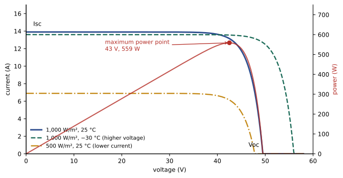
The current-voltage (I–V) curve describes a module's behaviour. At short circuit, current is maximum (\(I_{sc}\)) and voltage zero; at open circuit, voltage is maximum (\(V_{oc}\)) and current zero. Between them lies the maximum power point (\(V_{mp}\), \(I_{mp}\)), where the product of voltage and current is greatest. Current is roughly proportional to irradiance, the solar power arriving per square metre, with 1,000 W/m² as the standard test condition (STC) at a cell temperature of 25 °C. Voltage depends mainly on temperature: it rises as cells get colder, by about 0.25 to 0.35 % per °C for silicon. Power falls as temperature rises, so hot modules produce less.
String design and voltage limits
Modules are wired in series strings to reach the inverter's operating voltage, and strings are combined in parallel for more current. The maximum system voltage must never exceed the ratings of the modules, inverter and other components, and the code limit for the building type. Because voltage rises in cold weather, the maximum open circuit voltage is calculated at the lowest expected ambient temperature at the site, using the manufacturer's temperature coefficient of \(V_{oc}\):
where \(N\) is the number of modules in series, \(\beta\) is the coefficient in % per °C expressed as a fraction, and \(T_{min}\) is the minimum design temperature. The string must also stay above the inverter's minimum MPPT voltage on the hottest days, when \(V_{mp}\) is lowest.
Worked problem
Maximum modules per string
A module has Voc = 49.5 V and a Voc temperature coefficient of −0.27 %/°C. The site design low temperature is −35 °C, and the inverter maximum input is 600 V. How many modules can be connected in series?
Show solution
- Temperature difference: 25 − (−35) = 60 °C.
- Correction factor: 1 + 0.0027 × 60 = 1.162.
- Cold Voc per module: 49.5 × 1.162 = 57.5 V.
- Maximum modules: 600 / 57.5 = 10.4, so 10 modules (575 V).
- Check the hot-weather Vmp of 10 modules against the inverter's minimum MPPT voltage.
Answer: 10 modules per string, giving about 575 V at −35 °C.
Current calculations also include margins. Codes treat PV source circuit current as the short-circuit current multiplied by 125 % to account for irradiance above STC, and conductors and overcurrent devices are then sized at a further 125 % for continuous operation, giving 156 % of \(I_{sc}\) in many cases. Where more than two strings are paralleled, string fuses protect each string from backfeed current from the others.
In Canada, Section 64 of the Canadian Electrical Code covers renewable energy systems including PV, with rules for maximum voltage calculation, conductor sizing, disconnecting means, rapid shutdown, arc-fault protection and marking; installations also require utility interconnection approval under the distributor's requirements, and equipment certified to CSA or equivalent standards.
Inverters and system configurations
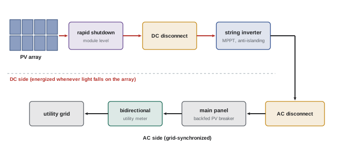
Inverters convert DC from the array to AC synchronized with the grid, and they track the maximum power point continuously as conditions change. The main types are:
- String inverters: one inverter serves one or more strings, with one or several MPPT inputs. Cost-effective for unshaded arrays with uniform orientation.
- Microinverters: a small inverter on each module converts to AC at the module, eliminating high-voltage DC on the roof and optimizing each module independently; more units to fail but excellent with shading and complex roofs.
- DC optimizers with a string inverter: module-level electronics that perform MPPT and support rapid shutdown, feeding a simplified string inverter.
- Central inverters: large units of hundreds of kilowatts to megawatts for utility-scale and large commercial systems.
- Hybrid or multimode inverters: also manage batteries and can supply backup loads during outages (Lesson 9).
Grid-tied inverters must stop exporting within a short time when the grid fails, called anti-islanding protection, so that utility workers are not endangered by a line energized from customer generation. Interconnection standards, such as IEEE 1547 and UL 1741 in the United States and CSA C22.2 No. 107.1 and C22.3 No. 9 in Canada, define these protective functions and, in newer versions, grid-support functions such as voltage and frequency ride-through.
Interconnection
A PV system connects to the building's electrical system either on the supply side of the service disconnect (a line-side tap) or on the load side through a backfed breaker in a panel. Load-side connections are limited so the panel busbar is not overloaded by the combined current from the utility and the inverter. A common rule permits the sum of the main breaker rating and 125 % of the inverter output current to reach 120 % of the busbar rating when the PV breaker is at the opposite end of the bus from the main.
Worked problem
Checking a load-side connection
A panel has a 200 A busbar and a 200 A main breaker. An inverter has a continuous output current of 32 A. Can it be connected with a backfed breaker at the opposite end of the bus under the 120 % rule?
Show solution
- 120 % of the busbar rating = 1.2 × 200 = 240 A.
- 125 % of inverter output = 1.25 × 32 = 40 A.
- Main breaker + 40 A = 200 + 40 = 240 A.
- 240 A ≤ 240 A, so the connection is permitted, using a 40 A backfed breaker.
- A larger inverter would require derating the main breaker, a supply-side connection, or a different method permitted by the code.
Answer: Yes, exactly at the 120 % limit with a 40 A breaker.
Rapid shutdown and arc-fault protection
Firefighters on a roof face DC conductors that remain energized whenever light falls on the array. Rapid shutdown requirements limit the voltage of conductors after a shutdown is initiated: in current North American rules, conductors outside the array boundary must drop to 30 V within 30 seconds, and inside the array to a lower hazard level achieved by module-level electronics or other listed systems. A clearly labelled initiation device, often the service disconnect or a dedicated switch, starts the shutdown. DC arc-fault circuit protection detects the signature of a series arc from a loose connection or damaged conductor and shuts down the circuit, because DC arcs do not self-extinguish at current zero the way AC arcs do and are a leading cause of PV fires.
Installation and safety practices
PV installation involves working at heights, on roofs and with energized DC circuits that cannot be de-energized while the sun shines. Practices include fall protection, covering modules or working at night or with rapid shutdown activated when terminating, never disconnecting connectors under load (DC arcs are sustained), and using only matched connectors of the same make and type, because mixing similar-looking connectors from different manufacturers is a known cause of overheating and fires. Conductors in roof areas are exposed to high temperatures and ultraviolet light, so PV wire or listed cable rated for sunlight and wet locations is used, with ampacity corrections for rooftop temperatures. Equipment grounding of module frames and racking, using listed bonding hardware, protects against shock from insulation faults.
Testing and commissioning
Commissioning follows standards such as IEC 62446-1. Tests include visual inspection; continuity of equipment grounding; polarity of each string; open circuit voltage of each string, compared with expected values corrected for temperature (strings that differ by more than a few percent may have a missing or reversed module); short-circuit current or operating current; insulation resistance of the DC circuits; and functional tests of the inverter, disconnects, rapid shutdown and anti-islanding. I–V curve tracers capture the full curve of each string and reveal shading, soiling, cracked cells and failed bypass diodes. Thermal imaging under load finds hot cells, connectors and fuses. Results are recorded as a baseline for future maintenance.
Production estimates and system performance
Customers usually want to know how much energy a system will produce. Annual production depends on the array's rated power, the solar resource at the site, the orientation and tilt of the modules, shading, temperature and system losses in wiring, inverters and soiling. A rough estimate multiplies array power by peak sun hours, the daily solar energy expressed as equivalent hours at 1,000 W/m², and by a performance ratio of about 0.75 to 0.85. A 10 kW array at a site averaging 4 peak sun hours per day with a performance ratio of 0.8 produces about 10 × 4 × 0.8 × 365 ≈ 11,700 kWh per year. Modelling tools such as PVWatts and PVsyst use hourly weather data and detailed loss models for more accurate predictions. In northern climates, snow cover reduces winter production, but cold temperatures improve efficiency, and steeper tilts help shed snow.
Monitoring systems record production from each inverter or module and alert owners to faults. A sudden drop on one string suggests a blown fuse, failed connector or tripped arc-fault detector; a gradual decline across the array suggests soiling or module degradation, typically about 0.5 % per year for quality modules.
Ground faults and insulation monitoring
PV arrays have large areas of conductors exposed to weather, so insulation faults are common: damaged cables pinched by racking, water in junction boxes, and degraded module backsheets. Inverters perform an insulation resistance test before connecting each morning and refuse to start if it is too low, and ground-fault detection shuts down the array when leakage current exceeds a threshold. Finding the fault involves measuring insulation resistance string by string with an insulation tester rated for the system voltage, with the strings isolated and the inverter disconnected, and then narrowing down to the module or cable responsible. Because PV strings generate voltage whenever lit, insulation testing requires care: short-circuiting the string with a rated switch during the test, or testing in low light, and following the tester manufacturer's PV procedures.
Labels are an important part of PV safety. Codes require markings at disconnects, combiner boxes, inverters and the service equipment identifying PV power sources, maximum DC voltage, rapid shutdown switches and the location of all sources of supply, so that anyone working on the system or responding to an emergency can quickly understand how the building is powered.
Common mistakes
MistakeCalculating string voltage at 25 °C.
InsteadCorrect Voc to the site's lowest design temperature.
MistakeMixing connector brands.
InsteadUse matched connectors from the same manufacturer and type.
MistakeDisconnecting PV connectors under load.
InsteadOpen the DC disconnect or inverter first; DC arcs persist.
MistakeBackfeeding a panel without checking the busbar.
InsteadApply the 120 % rule or another permitted method.
MistakeAssuming an array is dead because the inverter is off.
InsteadModules stay energized in light; verify with a meter.
Summary and key terms
- PV current follows irradiance; voltage rises as temperature falls.
- Maximum string voltage is calculated at the lowest site temperature.
- Circuit current uses 125 % of Isc, often 156 % for conductor sizing.
- String inverters, microinverters, optimizers and central inverters suit different sites.
- Anti-islanding stops export when the grid fails.
- The 120 % rule limits load-side backfed breakers.
- Rapid shutdown and DC arc-fault protection address firefighter and fire risks.
- Irradiance
- Solar power per square metre.
- Isc
- Short-circuit current of a module or string.
- Voc
- Open circuit voltage.
- Maximum power point
- Operating point with greatest power output.
- STC
- Standard test conditions: 1,000 W/m², 25 °C.
- String
- Modules connected in series.
- MPPT
- Maximum power point tracking.
- Anti-islanding
- Inverter shutdown when the grid fails.
- Rapid shutdown
- Reducing PV conductor voltage for emergency responders.
- Bypass diode
- Diode allowing current around shaded cells.
Practice problems
Work each problem on paper first, then reveal the answer to check.
How does PV voltage change in cold weather?
Show answer
It rises.
What are standard test conditions?
Show answer
1,000 W/m² and 25 °C cell temperature.
Voc 40 V, coefficient −0.30 %/°C, Tmin −20 °C: cold Voc?
Show answer
40 × 1.135 = 45.4 V.
Isc = 11 A. What current is used for conductor sizing?
Show answer
11 × 1.56 ≈ 17.2 A.
What does a microinverter eliminate on the roof?
Show answer
High-voltage DC wiring.
What is anti-islanding?
Show answer
Stopping export when the grid is down.
225 A bus, 200 A main: maximum inverter current under the 120 % rule?
Show answer
(270 − 200)/1.25 = 56 A.
Why are DC arcs dangerous?
Show answer
They do not self-extinguish at current zero.
Why compare string Voc values at commissioning?
Show answer
To find missing or reversed modules.
What reveals failed bypass diodes?
Show answer
I–V curve tracing or thermal imaging.
Lesson quiz · 5 questions
Score 60% or more to complete this lesson.
Create a free account to save your progress, take quizzes and earn a certificate.