
ELEC-410 · Lesson 11 of 12 · 25 min
Fire alarm interfaces and building automation
Modern buildings are full of interconnected systems: fire alarm, sprinklers, smoke control, elevators, access control, HVAC, lighting controls, emergency power and building automation. When a fire is detected, many of these must act together: fans shut down or switch to smoke control mode, doors held open by magnets release, elevators return to the recall floor, card readers unlock exit doors, and the generator starts if utility power fails. Electricians install much of the wiring that makes these interfaces work, and errors can defeat life safety functions. This lesson covers fire alarm system basics and circuit types, the common interfaces to other systems, building automation networks, wiring and survivability requirements, and the verification and testing that prove the integrated system works.
Fire alarm system basics
A fire alarm system detects fire and alerts occupants and, usually, the fire department. Its main parts are the fire alarm control unit (FACU, also called the control panel), initiating devices (smoke detectors, heat detectors, manual pull stations, sprinkler waterflow switches, duct detectors), notification appliances (horns, speakers, strobes), supervisory devices (sprinkler valve tamper switches, low-air switches), and connections to a monitoring station. Systems may be conventional, where devices on a zone circuit report as a group, or addressable, where each device has an address and reports its own status, allowing the panel to identify the exact location of an alarm.
Fire alarm systems distinguish three types of signals: alarm signals, which indicate fire and require evacuation or other action; supervisory signals, which indicate abnormal conditions in fire protection systems, such as a closed sprinkler valve; and trouble signals, which indicate faults in the fire alarm system itself, such as an open circuit, ground fault or power failure. Monitoring for integrity, also called supervision, is fundamental: the panel continuously checks that its circuits are intact, so a cut wire produces a trouble signal rather than silently disabling detection.
In Canada, the National Building Code and provincial building codes require fire alarm systems in many buildings; installation follows CAN/ULC-S524, verification follows CAN/ULC-S537, inspection and testing follow CAN/ULC-S536, and the Canadian Electrical Code Section 32 covers fire alarm wiring, including requirements for dedicated circuits supplying the control unit.
Circuit types and supervision
Fire alarm circuits are supervised using end-of-line devices or addressable polling. A conventional initiating device circuit (IDC) carries a small supervisory current through an end-of-line resistor; an open circuit lowers the current (trouble), and a device in alarm shorts the circuit through a resistance, raising current (alarm). Notification appliance circuits (NACs) are supervised by reversing polarity: in standby, a small reverse current flows through the end-of-line resistor while diodes in each appliance block it, and in alarm the panel reverses polarity to power the appliances. Addressable signalling line circuits (SLCs) communicate digitally with each device.
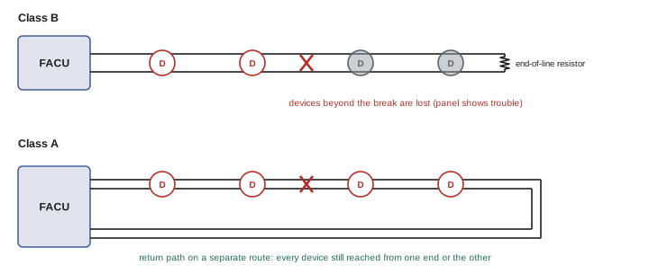
Circuit classes describe how circuits tolerate faults. Class B circuits run out to the last device and terminate in an end-of-line device; a single break disables devices beyond it, though the panel reports the trouble. Class A circuits loop back to the panel, so a single open still lets every device communicate from one direction or the other. Class X also tolerates short circuits by using isolator modules. Codes or designs specify the class for different circuits, and Class A wiring must follow separate routes for the outgoing and return conductors so that one incident does not damage both.
Interfaces to other building systems
Fire alarm systems control other systems through relays, addressable control modules or network gateways. Common interfaces include:
- HVAC shutdown: duct smoke detectors and the fire alarm stop air handling units to prevent smoke spreading, typically through a relay contact wired into the fan starter or VFD safety circuit, not merely a building automation command.
- Smoke control: in larger buildings, dedicated smoke control systems pressurize stairwells, exhaust smoke from the fire floor and position dampers, under a firefighter's smoke control panel.
- Door hold-open release: magnetic door holders on fire doors release when the fire alarm activates, so doors close to compartmentalize the building.
- Elevator recall: smoke detectors in elevator lobbies, machine rooms and hoistways signal the elevator controller to return cars to the designated recall floor (Phase I emergency recall), or to an alternate floor if smoke is detected at the main floor; heat detectors near sprinklers in machine rooms may trigger shunt trip of elevator power before water is discharged.
- Access control: electrically locked doors in the path of egress unlock on fire alarm, as required by building codes.
- Sprinkler monitoring: waterflow switches initiate alarms and valve tamper switches report supervisory signals; fire pump controllers report running, phase failure and other conditions.
- Kitchen hood suppression, clean agent systems and other special suppression systems report to the fire alarm system and may release only under specific sequences.
- Emergency communication: voice evacuation systems and mass notification systems broadcast instructions.
Each interface is defined in a sequence of operations or input/output matrix in the design documents, which lists every initiating event and the resulting actions. The matrix is the basis for programming and testing.
| Input | Fan shutdown | Door release | Elevator recall | Notify |
|---|---|---|---|---|
| Smoke detector, floor 3 corridor | AHU-3 off | Floor 3 doors | No | Building alarm |
| Duct detector, AHU-2 | AHU-2 off | No | No | Supervisory or alarm (per design) |
| Elevator lobby detector, floor 1 | No | Floor 1 doors | Recall to alternate floor | Building alarm |
| Sprinkler waterflow, zone 4 | All AHUs off | All doors | No | Building alarm |
| Valve tamper, zone 4 | No | No | No | Supervisory only |
Wiring and survivability
Fire alarm wiring must be installed so the system keeps working when needed. Requirements include dedicated circuits for the control unit, clearly identified and locked or protected against accidental switching off; fire alarm cables listed for the purpose, often with red jackets; separation of power-limited fire alarm circuits from other wiring; and survivability, the requirement in some buildings that circuits continue to operate for a specified time during a fire, achieved with two-hour rated cables, protected routes or enclosure in rated construction. Secondary power from batteries must operate the system for a specified standby period, often 24 hours, followed by a period of alarm operation, such as 5 or 30 minutes, and battery capacity is calculated from the standby and alarm currents of all devices.
Worked problem
Fire alarm battery calculation
A panel and devices draw 0.45 A in standby and 3.2 A in alarm. The system requires 24 hours standby followed by 5 minutes of alarm, with a 20 % safety factor. Find the minimum battery capacity.
Show solution
- Standby capacity: 0.45 A × 24 h = 10.8 Ah.
- Alarm capacity: 3.2 A × (5 / 60) h = 0.27 Ah.
- Total: 10.8 + 0.27 = 11.07 Ah.
- With 20 % safety factor: 11.07 × 1.2 = 13.3 Ah.
- Select the next standard battery size, for example 18 Ah.
Answer: At least 13.3 Ah; an 18 Ah battery would be chosen.
Building automation systems
Building automation systems (BAS), also called building management systems, control HVAC, lighting, metering and other systems through networked controllers, sensors and actuators. Controllers run programmed sequences, such as maintaining supply air temperature, resetting set points based on outdoor temperature, and scheduling occupancy. Common protocols are BACnet (ASHRAE 135), in its BACnet/IP and BACnet MS/TP (RS-485) forms, Modbus RTU and TCP, LonWorks in older buildings, KNX in some markets, and DALI for lighting control. Integration lets one system read and command others: the BAS may read meter data over Modbus, show fire alarm status through a read-only BACnet gateway, and command lighting through DALI.
BAS wiring includes RS-485 trunks, which must be daisy-chained (not star-wired), terminated at both ends with the specified resistors, biased at one point, and shielded with the shield grounded at one point; analog inputs and outputs using 0–10 V or 4–20 mA; and low-voltage 24 V AC power for controllers and actuators from Class 2 transformers. Life safety functions must not depend on the BAS: codes generally require fire alarm–initiated fan shutdown and smoke control to be performed by listed equipment and hard-wired or listed interfaces, while the BAS may only monitor fire alarm status. BAS networks are also cybersecurity targets and should be segmented from corporate networks, with default passwords changed.
Verification and integrated testing
Before a building is occupied, the fire alarm system is verified: every device is tested, every circuit checked for proper supervision, and every output confirmed against the input/output matrix. In Canada this is formal verification under CAN/ULC-S537 by a qualified technician; in the United States, acceptance testing under NFPA 72, witnessed by the authority having jurisdiction. Increasingly, integrated testing of fire protection and life safety systems, described in standards such as NFPA 4 and CAN/ULC-S1001, tests the systems together: activating a detector and confirming that the fans stop, dampers move, doors release, elevators recall and the generator picks up loads, in the correct sequence and timing. Integrated testing often reveals problems that individual system tests miss, such as a fan that restarts after a BAS command overrides a shutdown, or a door lock that stays locked because its power supply was not connected to the fire alarm relay.
Detector placement and wiring practices
Electricians installing fire alarm devices should follow the drawings and the device manufacturer's instructions closely, because detector placement affects performance. Smoke detectors are kept away from air supply diffusers that can blow smoke away, from dead air spaces in corners, and from areas where dust, steam or cooking cause false alarms; heat detectors or special detectors are used in such areas. Duct smoke detectors require sampling tubes oriented correctly to the airflow, and the pressure differential across the sampling tube should be checked to confirm air is flowing through the detector housing. Wiring is installed without splices where possible, with splices only in accessible boxes when necessary, and conductors are looped on device terminals rather than T-tapped on Class B circuits, because a T-tap creates a branch that the end-of-line device cannot supervise. Addressable devices must be set to the correct address and recorded on the as-built drawings so that an alarm displays the correct location.
Monitoring and response
Most fire alarm systems transmit signals to a monitoring station by digital communicator over telephone lines, cellular, IP networks or radio, with redundant paths so that one failed path is reported and does not prevent alarm transmission. The monitoring station dispatches the fire department on alarm signals and contacts the owner on supervisory and trouble signals. Electricians and technicians must notify the monitoring station before working on a system, to avoid false dispatches, and confirm that the system has been returned to normal and communicating before leaving the site.
Emergency lighting and exit signs
Emergency lighting systems illuminate exit routes when normal power fails. They may be supplied from a central generator or battery system through the emergency distribution, or from self-contained unit equipment with integral batteries, often called battery packs, that switch on automatically when the normal lighting circuit loses power. Unit equipment must be connected to the same branch circuit as the normal lighting in the area it serves, ahead of any local switch, so that it detects a loss of that circuit. Exit signs, usually LED, are illuminated continuously and must remain lit during power failure. Codes require monthly functional tests of short duration and annual tests of the full rated duration, often 30 minutes or more depending on the building code, with results recorded; self-testing units that perform these tests automatically and report failures reduce the maintenance burden.
Common mistakes
MistakeUsing a BAS command for fire alarm fan shutdown.
InsteadUse listed, hard-wired or listed interfaces from the fire alarm system.
MistakeRunning Class A return conductors with the outgoing pair.
InsteadRoute outgoing and return paths separately.
MistakeLeaving the fire alarm panel on an unmarked general circuit.
InsteadProvide a dedicated, identified, protected circuit.
MistakeStar-wiring RS-485 BAS networks.
InsteadDaisy-chain and terminate at both ends.
MistakeTesting each system separately only.
InsteadPerform integrated testing against the I/O matrix.
Summary and key terms
- Fire alarm systems detect, notify and monitor fire protection systems.
- Alarm, supervisory and trouble signals have different meanings.
- Supervision ensures faults produce trouble signals.
- Class A circuits survive a single open; Class B do not.
- Fire alarms control fans, doors, elevators, locks and suppression systems.
- Battery capacity covers standby and alarm periods with a safety factor.
- BAS integrates HVAC and lighting but must not perform life safety functions alone.
- FACU
- Fire alarm control unit.
- Initiating device
- Detector, pull station or switch that triggers a signal.
- Notification appliance
- Horn, speaker or strobe alerting occupants.
- Supervisory signal
- Abnormal condition in a fire protection system.
- Trouble signal
- Fault in the fire alarm system itself.
- End-of-line resistor
- Device enabling circuit supervision.
- Class A circuit
- Circuit returning to the panel, tolerating a single open.
- Elevator recall
- Returning elevators to a designated floor on fire alarm.
- Input/output matrix
- Table of events and resulting actions.
- BACnet
- Building automation communication protocol.
Practice problems
Work each problem on paper first, then reveal the answer to check.
Distinguish alarm, supervisory and trouble signals.
Show answer
Fire; abnormal protection system; fault in the alarm system.
What does an end-of-line resistor allow?
Show answer
Supervision of the circuit for opens.
How are NACs supervised?
Show answer
Reverse polarity current through an end-of-line resistor.
What advantage does Class A wiring have?
Show answer
Devices still work with a single open.
Name three fire alarm interfaces.
Show answer
Fan shutdown, door release, elevator recall, access control.
Why are elevators recalled to an alternate floor?
Show answer
Smoke detected at the main recall floor.
0.3 A standby 24 h, 2 A alarm 5 min, 20 % factor: capacity?
Show answer
(7.2 + 0.17) × 1.2 ≈ 8.8 Ah.
Name two BAS protocols.
Show answer
BACnet, Modbus, LonWorks, KNX, DALI.
How should RS-485 be wired?
Show answer
Daisy-chained, terminated at both ends.
What does integrated testing check?
Show answer
That interconnected systems act together correctly.
Lesson quiz · 5 questions
Score 60% or more to complete this lesson.
Create a free account to save your progress, take quizzes and earn a certificate.