
ELEC-410 · Lesson 7 of 12 · 24 min
Hazardous locations and intrinsic safety
Refineries, gas plants, grain elevators, paint booths, wastewater lift stations, distilleries and many chemical plants contain flammable gases, vapours, dusts or fibres that an electrical spark or hot surface could ignite. Electrical equipment in these hazardous (classified) locations must be designed and installed so that it cannot cause an ignition. This lesson explains how hazardous locations are classified, the protection methods used for equipment, the details of intrinsic safety that instrumentation relies on, and installation requirements such as seals and equipment marking. The rules are detailed and code-specific, and work in classified areas should always follow the current code, the area classification drawings and the manufacturer's certification documents.
The fire triangle and ignition
An explosion requires fuel, an oxidizer (usually air) and an ignition source, with the fuel concentration between its lower and upper flammable limits. Methane, for example, burns between about 5 % and 15 % by volume in air. Electrical ignition sources include arcs and sparks from switches, contacts and loose connections, hot surfaces of motors, lights and heaters, and static discharges. Each flammable material has a minimum ignition energy, which for hydrogen is tiny, far less than the energy of a static spark you can feel, and an autoignition temperature at which it ignites from a hot surface without a spark. Hazardous location equipment works by keeping one side of the triangle away: containing an explosion, excluding the flammable atmosphere, or limiting energy and temperature so ignition cannot occur.
Classification: divisions and zones
North American practice historically classified locations by Class and Division. Class I covers flammable gases and vapours, Class II combustible dusts and Class III ignitable fibres and flyings. Division 1 means the hazard is likely to be present under normal operating conditions; Division 2 means it is present only under abnormal conditions such as a leak or equipment failure. Gases are grouped by how easily they ignite and how hard their explosions are to contain: Group A (acetylene), B (hydrogen), C (ethylene) and D (propane, methane, gasoline). Dusts are Groups E (metals), F (carbonaceous) and G (grain, plastics, flour).
The international zone system, from IEC 60079 and adopted widely, divides gas atmospheres into Zone 0 (present continuously or for long periods), Zone 1 (likely in normal operation) and Zone 2 (not likely, and only briefly if it occurs). Dust atmospheres use Zones 20, 21 and 22. Gas groups are IIC (hydrogen, acetylene, the most demanding), IIB (ethylene) and IIA (propane, methane).
In Canada, Section 18 of the Canadian Electrical Code uses the zone system for Class I locations (Zones 0, 1 and 2) and recent editions add Zones 20, 21 and 22 for combustible dusts, while Annex J provides the division-based rules for existing facilities that remain classified by division.
Area classification is an engineering task, documented on drawings that show the boundaries of each zone or division around sources of release such as pump seals, vents, flanges and open tanks, based on standards and recommended practices such as API RP 500 and 505 or IEC 60079-10. Electricians do not classify areas, but they must read the drawings and select and install equipment accordingly.
| Hazard presence | Division system | Zone system (gas) | Zone system (dust) |
|---|---|---|---|
| Continuous or long periods | Division 1 | Zone 0 | Zone 20 |
| Likely in normal operation | Division 1 | Zone 1 | Zone 21 |
| Only abnormal, short duration | Division 2 | Zone 2 | Zone 22 |
Temperature classes
Equipment is marked with a temperature class (T-code) showing its maximum surface temperature, which must be below the autoignition temperature of the materials present. T1 allows up to 450 °C, T2 300 °C, T3 200 °C, T4 135 °C, T5 100 °C and T6 85 °C, with intermediate classes such as T2A to T4A in North American division marking. Gasoline vapour autoignites around 280 °C, so equipment must be T3 or better; carbon disulfide, at about 90 °C, needs T6. Dust layers insulate hot surfaces and can smoulder, so dust equipment is rated by maximum surface temperature with dust layers considered.
Protection methods
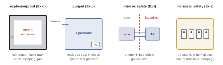
Different protection techniques suit different equipment and zones:
- Explosionproof or flameproof (Ex d): the enclosure is strong enough to contain an internal explosion, and joints are long, narrow flame paths that cool escaping gases below ignition temperature. Common for motors, switches, junction boxes and luminaires. Flame path surfaces must not be scratched, painted or gasketed unless approved, and every cover bolt must be installed.
- Increased safety (Ex e): equipment that does not normally spark, such as terminal boxes and some motors, is built with extra measures against arcs and hot spots; used in Zone 1 often in combination with flameproof components.
- Purged and pressurized (Ex p; Types X, Y and Z in NFPA 496): an enclosure or room is kept at positive pressure with clean air or inert gas, with interlocks to de-energize equipment if pressure is lost. Used for analyser shelters, control rooms and large motors.
- Intrinsic safety (Ex i): energy in the circuit is limited so that no spark or hot surface can ignite the atmosphere even under faults. The preferred method for instrumentation.
- Non-incendive and type n (Ex n, Ex ec, Ex nA): equipment that does not spark or get hot in normal operation, acceptable in Division 2 or Zone 2.
- Encapsulation (Ex m), oil or liquid immersion (Ex o) and powder filling (Ex q) cover specialized components.
- Dust ignition-proof enclosures (Ex t) exclude dust and limit surface temperature.
Intrinsic safety
An intrinsically safe (IS) system limits voltage, current and stored energy in field wiring below the levels that could ignite the specified gas group, even with up to two faults (category ia, suitable for Zone 0) or one fault (ib). Because energy is limited, IS equipment can be serviced live in the hazardous area, uses ordinary-looking instrument enclosures, and suits low-power devices like transmitters, switches and solenoids designed for IS.
An IS system has three parts: the IS field device (intrinsically safe apparatus), the associated apparatus in the safe area that limits energy, and the interconnecting cable. Associated apparatus is either a zener barrier or a galvanic isolator. A zener barrier uses resistors to limit current, zener diodes to clamp voltage and a fuse to protect the zeners; it must be connected to a high-integrity intrinsically safe ground, usually with a resistance of 1 Ω or less to the grounding system, because fault current is diverted to ground. A galvanic isolator transfers signal and power through transformers or optocouplers, needs no special IS ground, isolates ground loops and is now more common, at higher cost.
Compatibility between apparatus and barrier is checked with the entity concept. The barrier is marked with its maximum output voltage \(U_o\) (or \(V_{oc}\)), current \(I_o\) (or \(I_{sc}\)), and the maximum capacitance \(C_o\) and inductance \(L_o\) it can safely connect to. The field device is marked with its maximum input values \(U_i\), \(I_i\) and internal \(C_i\), \(L_i\). The system is safe if:
Worked problem
Entity parameter check
A barrier has Uo = 28 V, Io = 93 mA, Co = 0.13 µF, Lo = 4.2 mH for group IIC. A transmitter has Ui = 30 V, Ii = 100 mA, Ci = 10 nF, Li = 0. The cable is 300 m with 200 pF/m and 0.66 µH/m. Is the loop acceptable?
Show solution
- Voltage: Ui 30 V ≥ Uo 28 V — acceptable.
- Current: Ii 100 mA ≥ Io 93 mA — acceptable.
- Capacitance: cable 300 × 200 pF = 60 nF; plus Ci 10 nF = 70 nF ≤ Co 130 nF — acceptable.
- Inductance: cable 300 × 0.66 µH = 0.198 mH; plus Li 0 = 0.198 mH ≤ 4.2 mH — acceptable.
- Record the calculation on the IS loop documentation.
Answer: All four entity conditions are met, so the loop is acceptable.
IS wiring is installed so it cannot pick up energy from other circuits. Codes require IS conductors to be separated from non-IS conductors, typically by 50 mm of clear space or by grounded metal partitions or insulating barriers in terminal boxes and cabinets, with IS terminals separated from non-IS terminals. IS wiring and terminals are commonly identified with light blue colour. Any modification, even replacing a device with a similar one, requires rechecking certification and entity parameters, because a substituted part can invalidate the system.
Wiring methods, seals and marking
Wiring methods in classified areas are restricted: rigid metal conduit with threaded joints, mineral-insulated cable, and listed cables such as armoured cable with appropriate glands are common in Division 1 and Zone 1, with wider options in Division 2 and Zone 2. Conduit seals, filled with special compound, prevent flames and gases travelling through conduit between explosionproof enclosures or from hazardous to non-hazardous areas. Seals are required within specified distances of enclosures containing arcing devices and at boundaries, and the compound must be poured correctly with the fibre dam in place and allowed to cure; an empty or poorly poured seal is a common inspection finding. Cable glands for armoured cables must be of the certified type, often with barrier compound for Zone 1.
Equipment must be certified for the location and marked accordingly. A North American division marking might read "Class I, Division 1, Groups C and D, T4", while a zone marking might read "Ex db IIB T4 Gb", indicating flameproof protection, gas group IIB, temperature class T4 and equipment protection level Gb (suitable for Zone 1). Equipment protection levels Ga, Gb and Gc correspond to Zones 0, 1 and 2, and Da, Db and Dc to dust zones 20, 21 and 22. Inspectors check that the marking matches the classification drawing for every item.
Maintenance and work practices
Work in hazardous locations requires permits, gas testing before and during hot work, and attention to details that keep protection intact: replacing all bolts on flameproof covers, not using unapproved sealants on flame paths, keeping gaskets on increased safety enclosures in good condition, restoring purge systems before energizing, and not opening explosionproof enclosures while energized unless the area is confirmed gas-free under a permit. Periodic inspection programmes, following standards such as IEC 60079-17, record the condition of each item. Portable tools, radios, phones and test instruments brought into classified areas must also be suitable, for example intrinsically safe multimeters and calibrators.
Inspection findings and documentation
Inspections in hazardous areas commonly find unused entries left open on explosionproof enclosures, missing or loose cover bolts, corroded or painted flame paths, wrong cable glands, unsealed conduits, non-certified equipment added during maintenance, and IS circuits modified without documentation. A hazardous area dossier, maintained for each facility, holds the classification drawings, the equipment register with certification and marking for each item, IS loop calculations, inspection records and qualifications of personnel. Some jurisdictions and employers require specific competency certification for hazardous area work, such as IECEx personnel certification, in addition to an electrical licence.
Portable gas detectors give workers direct warning of flammable atmospheres before and during work. They are bump-tested daily with a known gas concentration to confirm they respond, calibrated at intervals set by the manufacturer, and worn in the breathing zone. A typical alarm is set at 10 % of the lower explosive limit, well below the concentration at which ignition becomes possible, giving time to stop work and leave the area.
Common mistakes
MistakeChoosing equipment without checking the classification drawing.
InsteadMatch zone or division, group and T-code for every item.
MistakeLeaving out cover bolts on explosionproof enclosures.
InsteadInstall every bolt; flame paths depend on them.
MistakeMixing IS and non-IS wiring in one terminal block.
InsteadSeparate by 50 mm or approved barriers, identified in light blue.
MistakeGrounding a zener barrier casually.
InsteadProvide a high-integrity IS ground or use isolators.
MistakeLeaving conduit seals unpoured.
InsteadInstall dams and pour compound correctly before energizing.
Summary and key terms
- Ignition needs fuel within flammable limits, air and an ignition source.
- Divisions 1 and 2 or Zones 0, 1, 2 (and 20, 21, 22) classify hazard likelihood.
- Gas groups and temperature classes restrict equipment selection.
- Protection methods contain, exclude or limit energy.
- Intrinsic safety limits energy with barriers or isolators.
- Entity parameters confirm barrier, device and cable compatibility.
- Seals, certified glands and correct marking are inspection essentials.
- Hazardous location
- An area where flammable atmospheres may occur.
- Division 1
- Hazard likely under normal conditions.
- Zone 0
- Explosive gas atmosphere present continuously.
- Gas group
- Classification of gases by ignition behaviour.
- Temperature class
- Maximum surface temperature code of equipment.
- Explosionproof
- Enclosure that contains an internal explosion.
- Intrinsic safety
- Protection by limiting circuit energy.
- Zener barrier
- Associated apparatus limiting voltage and current.
- Entity parameters
- Ratings used to check IS loop compatibility.
- Conduit seal
- Compound-filled fitting stopping gas and flame travel.
Practice problems
Work each problem on paper first, then reveal the answer to check.
What are the flammable limits of methane?
Show answer
About 5 % to 15 % in air.
Define Division 2.
Show answer
Hazard present only under abnormal conditions.
Which zone means continuous presence of gas?
Show answer
Zone 0.
Which gas group is most demanding?
Show answer
IIC (Group A/B in division terms).
Maximum surface temperature for T4?
Show answer
135 °C.
How does explosionproof protection work?
Show answer
Contains explosions; flame paths cool escaping gas.
Why does a zener barrier need a good ground?
Show answer
Fault current is diverted to ground.
List the four entity conditions.
Show answer
Ui ≥ Uo, Ii ≥ Io, Ci + Ccable ≤ Co, Li + Lcable ≤ Lo.
What colour identifies IS wiring?
Show answer
Light blue.
Decode Ex db IIB T4 Gb.
Show answer
Flameproof, gas group IIB, T4, Zone 1 protection level.
Lesson quiz · 5 questions
Score 60% or more to complete this lesson.
Create a free account to save your progress, take quizzes and earn a certificate.