
ELEC-410 · Lesson 10 of 12 · 26 min
Electric vehicle charging equipment
Electric vehicles (EVs) have turned charging stations into routine electrical work in homes, apartment and condominium buildings, workplaces, fleet depots and highway sites. A single charger can be the largest load in a house, and dozens of chargers can exceed the capacity of a building's service. This lesson explains charging levels and connector standards, how EV supply equipment communicates with vehicles, branch circuit and load calculations, energy management systems that let more chargers share limited capacity, protection and installation requirements, DC fast charging, and commissioning and troubleshooting.
Charging levels and connectors
Charging is described by levels:
- Level 1: charging from a standard 120 V receptacle at 12 to 16 A, about 1.4 to 1.9 kW, adding roughly 6 to 8 km of range per hour. Adequate for plug-in hybrids and low daily mileage.
- Level 2: charging at 208 or 240 V single-phase, commonly 32 to 48 A (7.7 to 11.5 kW), and up to 80 A (19.2 kW), adding roughly 40 to 70 km per hour. The standard for homes, workplaces and destinations.
- DC fast charging (sometimes called Level 3): an off-board charger converts AC to DC and supplies the battery directly at 50 to 350 kW or more, adding hundreds of kilometres in 20 to 40 minutes.
With AC charging, the vehicle's on-board charger converts AC to DC, and its rating limits the charging rate: a car with a 7.2 kW on-board charger will not charge faster on an 11.5 kW station. North American connectors include the SAE J1772 connector for AC charging, CCS1 (Combined Charging System), which adds two DC pins below the J1772 connector, and the North American Charging Standard (NACS), standardized as SAE J3400, which handles both AC and DC in one compact connector and is being adopted by most manufacturers. CHAdeMO is a legacy DC standard. Adapters allow cross-compatibility, but the installed station must be listed for its connector and use.
| Level | Supply | Typical power | Range added per hour |
|---|---|---|---|
| Level 1 | 120 V, 12–16 A | 1.4–1.9 kW | About 6–8 km |
| Level 2 | 208/240 V, 32–80 A | 6.6–19.2 kW | About 40–100 km |
| DC fast | 3-phase AC to off-board charger | 50–350 kW | Hundreds of km in 20–40 min |
How EVSE communicates with the vehicle
The wall unit for AC charging is properly called electric vehicle supply equipment (EVSE): it does not charge the battery itself but safely supplies AC power to the vehicle's charger. Before energizing the cable, the EVSE and vehicle communicate through the control pilot, a ±12 V, 1 kHz pulse-width-modulated signal defined in SAE J1772. The pilot voltage changes as the vehicle is connected (9 V) and requests charging (6 V), and the duty cycle tells the vehicle the maximum current it may draw: for currents from 6 to 51 A, the allowed current is the duty cycle percentage multiplied by 0.6. A proximity circuit detects that the connector is latched. Only after this handshake does the EVSE close its contactor. The EVSE also continuously monitors for ground faults with a charging circuit interrupting device (CCID) that trips at about 20 mA, and opens if the pilot signal is lost.
Worked problem
Reading the pilot duty cycle
An EVSE on a 40 A circuit is configured to offer 32 A. What pilot duty cycle should be measured, and what breaker and conductor rating are required?
Show solution
- Duty cycle = 32 / 0.6 = 53.3 %.
- EV charging is a continuous load, so the circuit is rated at 125 % of 32 A = 40 A.
- A 40 A breaker and conductors rated at least 40 A (after corrections) are required.
- A pilot measuring 53 % confirms the EVSE is set correctly; a different value means the setting does not match the circuit.
Answer: About 53 % duty cycle on a 40 A circuit.
Branch circuits and load calculations
EVSE is treated as a continuous load, so the branch circuit and overcurrent device are rated at least 125 % of the EVSE's maximum current: a 48 A EVSE needs a 60 A circuit. Each EVSE is normally supplied by an individual branch circuit. Many Level 2 units are hardwired; plug-in units use receptacles such as NEMA 14-50 or 6-50, which must be suitable for repeated EV charging duty, since low-quality receptacles have overheated under hours of continuous load.
Adding EV charging to an existing building requires a load calculation to confirm the service and feeders can supply the additional load. A house with a 100 A service and electric range, dryer and water heater may not have room for a 48 A charger at full rating; the options are a smaller charger setting, a load management device, or a service upgrade. Multi-unit residential buildings face this problem at scale, because providing full-rate dedicated circuits to every parking space can require service capacity many times larger than the building's existing load.
In Canada, Section 86 of the Canadian Electrical Code covers electric vehicle charging systems, requiring that EVSE be supplied by a separate branch circuit and treated as continuous load, while Rule 8-500 permits electric vehicle energy management systems (EVEMS) to limit the load so that the calculated demand of EV charging can be reduced; many provinces and cities now require new residential buildings to provide energized outlets or conduits for EV charging in parking spaces.
Energy management systems
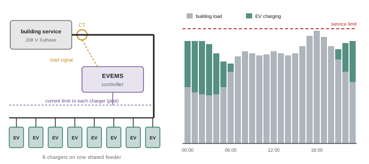
An EV energy management system (EVEMS, or load management) monitors the building load or a group of chargers and adjusts each charger's pilot signal so the total never exceeds a set limit. Approaches include:
- Load sharing: several chargers on one circuit or feeder divide a fixed current; two 40 A chargers sharing a 40 A allowance each get 20 A when both are in use and 40 A when only one is.
- Dynamic load management: a current sensor on the service measures building load and gives chargers whatever capacity remains, reducing or pausing charging when other loads peak.
- Networked management: cloud-connected chargers use protocols such as the Open Charge Point Protocol (OCPP) to schedule charging, respond to utility time-of-use rates and demand response signals, and bill users.
Because vehicles typically park for many hours overnight, even a modest share of capacity per vehicle delivers enough energy: 3.3 kW for 10 hours adds 33 kWh, roughly 200 km of driving. Energy management therefore lets a building serve many more charging spaces than a simple load calculation would allow.
Worked problem
Chargers on a limited service
An apartment building has 120 kVA of spare capacity at night on a 208 V three-phase service. How many 7.2 kW Level 2 chargers can run simultaneously at full rate, and how could 40 parking spaces be served?
Show solution
- Treat chargers as unity power factor: 120 kVA ≈ 120 kW available.
- Full-rate chargers: 120 / 7.2 = 16.7, so 16 chargers at full rate.
- With an EVEMS sharing capacity among 40 chargers: 120 / 40 = 3 kW each when all are charging.
- Over a 10-hour night, each vehicle receives about 30 kWh even if all charge at once, enough for most daily driving.
- Balance chargers across the three phases so no phase is overloaded.
Answer: 16 at full rate; with load management, all 40 spaces can be served at about 3 kW each when all are active.
Protection and installation
Ground-fault protection for personnel is required for EV charging, either built into the EVSE (the CCID) or provided by the branch circuit, depending on the equipment and code. Outdoor EVSE must be rated for the location, and pedestals in parking lots need protection from vehicle impact with bollards or wheel stops. Cable management keeps charging cables off the ground where they could be damaged or cause trips. Accessibility requirements may govern the height and location of controls and connectors in public installations. Ventilation was once required for indoor charging of batteries that released hydrogen, but listed EVSE for modern vehicles generally indicates that ventilation is not required. Conductors are sized for the continuous load, with voltage drop considered for long runs to parking areas; a 5 % drop at 48 A on a 240 V circuit reduces charging power noticeably and wastes energy.
DC fast charging
DC fast chargers are large power electronics systems, typically supplied at 480 V three-phase in the United States or 600 V in Canada, often from a dedicated utility transformer, with feeders of hundreds of amperes per charger. Sites with several high-power chargers may require medium-voltage service, switchgear and careful coordination with the utility, and demand charges can dominate operating costs, which is why some sites add battery storage to reduce peaks. The charger communicates digitally with the vehicle over power-line communication on the control pilot (ISO 15118 and DIN 70121) to negotiate voltage and current as the battery charges. Installation includes structural pads, liquid cooling for high-power cables, network connectivity and payment systems, and accessibility. Maintenance focuses on cable and connector wear, cooling systems and uptime, which is now subject to reliability requirements under some public funding programs.
Commissioning and troubleshooting
Commissioning an EVSE installation includes verifying the circuit rating and the EVSE's configured maximum current (often set by DIP switches, a rotary switch or an app to match the breaker), torque on terminations, ground continuity, and a functional test with an EVSE tester or a vehicle. EVSE testers simulate a vehicle, display pilot states and duty cycle, and can simulate ground faults. Common problems include: chargers that trip on ground fault due to moisture in outdoor connections or a wiring error; incorrect current settings that either underuse the circuit or overload it; network and Wi-Fi failures for smart chargers; vehicles that charge slowly because the on-board charger limits power or the EVEMS is limiting; and overheating at loose terminals or worn receptacles, which thermal imaging finds before damage occurs.
Fleet and workplace charging
Fleet depots for buses, delivery vans and utility vehicles concentrate large charging loads in one place. A depot charging 50 electric buses overnight at 60 to 150 kW each may need several megawatts of capacity, requiring a new utility service at medium voltage, on-site switchgear and transformers. Fleet operators use managed charging to stagger sessions through the night, prioritizing vehicles by departure time and state of charge, which keeps peak demand far below the sum of charger ratings. Workplace charging is usually Level 2 with sharing, because vehicles are parked for most of the working day. Planning conduit and space for future chargers during initial construction is much cheaper than trenching later.
Accessibility, signage and user experience
Public chargers must be easy and safe to use. Clear signage identifies charging spaces and any time limits; pavement markings and wheel stops keep vehicles positioned so cables reach without strain. Accessible charging spaces follow accessibility standards for space width, access aisles and the reach height of controls and connectors, and at least some chargers at a site are normally required to be accessible. Payment options, including contactless cards rather than only apps or memberships, are increasingly expected or required, and screens must be readable in sunlight. Reliability matters as much as installation quality: a charger that is out of service frustrates drivers and undermines confidence, so owners increasingly use remote monitoring to detect faults and dispatch technicians promptly.
Common mistakes
MistakeSizing the circuit at 100 % of the charger current.
InsteadUse 125 % for continuous load.
MistakeLeaving the EVSE set above the breaker rating.
InsteadConfigure the maximum current to match the circuit.
MistakeAdding chargers without a load calculation.
InsteadCheck service capacity or use an EVEMS.
MistakeUsing a general-purpose receptacle for daily charging.
InsteadUse heavy-duty rated receptacles or hardwire.
MistakeUnbalanced chargers on a three-phase service.
InsteadDistribute chargers across phases.
Summary and key terms
- Level 1 is 120 V, Level 2 is 208/240 V, DC fast charging bypasses the on-board charger.
- J1772, CCS1 and NACS (SAE J3400) are North American connectors.
- The control pilot duty cycle sets maximum current (duty % × 0.6 A).
- EVSE is a continuous load requiring 125 % circuit rating.
- Energy management systems let many chargers share limited capacity.
- Ground-fault protection, location ratings and impact protection are required.
- DC fast charging needs large services, utility coordination and digital communication.
- EVSE
- Equipment that safely supplies power to a vehicle.
- On-board charger
- Vehicle converter for AC charging.
- Control pilot
- PWM signal communicating charging current.
- CCID
- Ground-fault device in EVSE tripping near 20 mA.
- J1772
- Standard AC charging connector.
- NACS
- North American Charging Standard connector, SAE J3400.
- CCS
- Combined Charging System for AC and DC.
- EVEMS
- Energy management system limiting charging load.
- OCPP
- Open Charge Point Protocol for networked chargers.
- DC fast charger
- Off-board charger supplying DC directly.
Practice problems
Work each problem on paper first, then reveal the answer to check.
Power of a 40 A Level 2 charger at 240 V?
Show answer
9.6 kW.
Why does a 7.2 kW on-board charger limit charging?
Show answer
AC charging cannot exceed the on-board charger rating.
Pilot duty cycle for 24 A?
Show answer
40 %.
Breaker for a 48 A EVSE?
Show answer
60 A.
What does the CCID do?
Show answer
Trips on ground fault at about 20 mA.
Two 32 A chargers share a 32 A allowance. Current each when both charge?
Show answer
16 A.
Energy from 3.3 kW over 8 hours?
Show answer
26.4 kWh.
What protocol connects networked chargers?
Show answer
OCPP.
What standard governs digital DC charging communication?
Show answer
ISO 15118 or DIN 70121.
Name a cause of nuisance ground-fault trips.
Show answer
Moisture in outdoor connections or wiring errors.
Lesson quiz · 5 questions
Score 60% or more to complete this lesson.
Create a free account to save your progress, take quizzes and earn a certificate.