
ELEC-310 · Lesson 9 of 12 · 27 min
Reversing, jogging, sequence and interlocking circuits
With the three-wire start-stop circuit as a foundation, a small number of standard circuits cover most motor control needs: reversing a motor, jogging it for setup, starting and stopping several motors in a required order, changing speed on two-speed motors, and stopping quickly with braking. Each circuit uses interlocks, contacts that prevent one action while another is in progress, to keep the machine and the electrical equipment safe. This lesson explains these standard circuits, how their interlocks work, and the faults that each interlock prevents.
Reversing starters
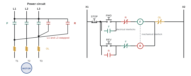
A three-phase induction motor reverses when any two supply lines are interchanged (Lesson 2). A reversing starter uses two contactors, forward (F) and reverse (R), sharing one overload relay. The forward contactor connects L1, L2 and L3 to T1, T2 and T3; the reverse contactor connects L3 to T1 and L1 to T3, with L2 to T2 in both. If both contactors closed at once, L1 and L3 would be connected together through the contacts: a line-to-line short circuit. Everything about the design of a reversing starter is about making that impossible.
Three kinds of interlock are used, usually together:
- Mechanical interlock: a lever or cam between the two contactors physically prevents one from closing while the other is closed. Factory-assembled reversing starters always include one.
- Electrical (auxiliary contact) interlock: an NC auxiliary contact of the reverse contactor is wired in series with the forward coil, and an NC auxiliary contact of the forward contactor in series with the reverse coil. Each coil can only energize if the other contactor is open.
- Pushbutton interlock: double-circuit (NO and NC) pushbuttons, with the NC contact of the forward button in series with the reverse coil and vice versa. Pressing forward opens the reverse circuit before closing the forward circuit, allowing a direct change of direction without pressing stop first.
With pushbutton interlocking, pressing reverse while running forward drops the forward contactor and immediately energizes the reverse contactor, applying reverse rotation to a motor still turning forward. This is plugging: the motor brakes hard and then accelerates in reverse, drawing more than locked-rotor current and imposing heavy mechanical shock on the load. Unless the motor and machine are designed for plugging, the circuit should require a stop and a pause before reversing, using only the electrical interlock, or an anti-plugging circuit that uses a zero-speed switch or timer to block reversal until the motor has stopped.
Worked problem
Diagnosing a reversing starter fault
On a reversing starter with electrical and mechanical interlocks, the motor runs forward normally. After stop is pressed, pressing reverse does nothing, although the reverse coil measures correct resistance. Pressing forward again works. What should be checked?
Show solution
- The reverse rung contains the stop button (working, since forward works), the reverse start button, the NC F interlock contact, the R coil and the shared overload contact (working).
- With power on and the motor stopped, measure voltage across the reverse start button while pressing it: if voltage disappears, the button is closing.
- Measure voltage across the NC F interlock contact: if the full control voltage appears across it with reverse pressed, the contact is open even though F is de-energized, indicating a faulty auxiliary contact or a mechanically stuck F contactor.
- Also confirm the mechanical interlock is free, since a jammed interlock can block R.
Answer: The most likely causes are a failed NC F interlock contact, a stuck F contactor or a jammed mechanical interlock. Measuring voltage across each element of the reverse rung in turn locates the open point quickly (Lesson 12).
Jogging
Jogging (or inching) means running a motor briefly, only while a button is held, to position a machine for setup, threading material or maintenance. The jog circuit must prevent the seal-in contact from latching the motor on. Common methods are:
- Selector switch: a run-jog selector switch opens the seal-in circuit in the jog position, so the start button acts as a jog button.
- Jog pushbutton with NC contact: a double-circuit jog button whose NC contact is in series with the seal-in contact and whose NO contact is in parallel with the start button. Pressing jog energizes the coil through the NO contact while the NC contact opens the seal-in path. The weakness is a race: if the button is released quickly, the NC contact may close before the starter's seal-in contact opens, latching the motor on.
- Control relay: the most reliable method. The start button energizes a control relay CR, which seals itself in and energizes the starter; the jog button energizes the starter directly without involving CR, so there is no seal-in path during jogging.
Jogging is severe duty for contactors (Lesson 6) and heats motors because each jog draws starting current. Where frequent jogging is needed, a drive with a jog speed is much better.
Sequence control
Many processes require motors to start and stop in a specific order. In a conveyor system feeding material from one conveyor to the next, the downstream conveyor must start first and stop last, so that material is never dropped onto a stopped belt. Similarly, a lubrication pump may need to run before a main drive can start, or a cooling fan before a heater. Sequence control enforces these permissives:
- Manual sequence: an NO auxiliary contact of the first starter is placed in series with the start circuit of the second, so the second cannot start until the first is running, and stopping the first stops the second as well.
- Automatic sequence: auxiliary contacts and on-delay timers start each motor automatically a set time after the previous one, which also spreads out the inrush currents.
- Process permissives: proof that the first machine is actually working, not just that its contactor is closed. Zero-speed switches on conveyors, flow switches on pumps and pressure switches on lubrication systems give this proof, because a contactor can be closed while the belt has snapped or the pump has lost prime.
Worked problem
Designing a conveyor sequence
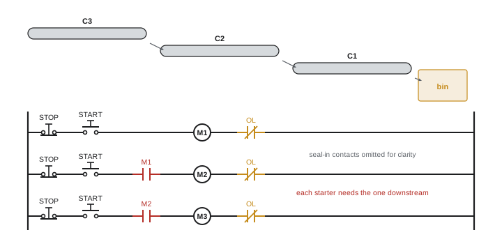
Three conveyors carry material: C3 feeds C2, which feeds C1, which discharges into a bin. Design the sequence logic so that the conveyors start in the safe order and an overload on any conveyor stops all conveyors feeding it.
Show solution
- Safe start order: C1 first (it discharges to the bin), then C2, then C3. Safe stop order: C3 first.
- M1 has a normal three-wire start-stop circuit.
- M2's rung includes an NO M1 auxiliary contact in series, so M2 can only run while M1 runs. M3's rung includes an NO M2 auxiliary contact.
- If C1 overloads, M1 drops out, its contact opens M2's rung, M2 drops out, which opens M3's rung: all three stop, so no material piles up. If C3 overloads, only C3 stops, which is safe.
- Better: use zero-speed switches on C1 and C2 in place of (or in addition to) the auxiliary contacts, so a broken belt also stops upstream conveyors.
Answer: Each conveyor's starter is permissive on the conveyor it feeds, enforcing the start order and stopping upstream conveyors when any downstream conveyor stops. Proof of motion from zero-speed switches makes the interlock reliable.
Limit switch control and automatic reversing
Limit switches can stop a motor at the end of travel, and can automatically reverse it for reciprocating machines such as shuttle tables. A typical arrangement uses an NC limit switch in series with each direction's coil, so the forward contactor drops out when the carriage reaches the forward limit; for automatic reversal, an NO contact of the same limit switch is placed in parallel with the reverse start button, so reaching the forward limit also starts the reverse motion. Overtravel limit switches beyond the normal limits, wired to stop all motion, provide protection if a normal limit fails. On hoists and cranes, upper and lower limit switches are safety devices and must never be bypassed.
Two-speed motors
Some loads, such as fans, cooling towers and machine tools, need two fixed speeds. Two-speed squirrel-cage motors come in two types:
- Separate winding: two independent stator windings with different numbers of poles, for example 4-pole and 6-pole (1,800 and 1,200 rpm synchronous); any speed ratio is possible, but the motor is larger for its rating.
- Consequent pole: a single winding that can be reconnected to double the number of poles, giving a 2:1 speed ratio, for example 1,800 and 900 rpm. Consequent-pole motors are classified as constant torque, variable torque or constant horsepower according to how the winding is reconnected, matching the load type.
The two-speed starter has a contactor for each speed (for consequent-pole motors, the high-speed connection needs extra contacts to short leads together) with separate overload relays sized for each speed's full-load current. Control circuits are interlocked like reversing starters so both speeds cannot be energized at once. Additional circuits are common: compelling control, which requires the motor to start in low speed before high speed can be selected, reducing inrush; accelerating control, which steps to high speed automatically after a delay; and decelerating control, which requires a pause before changing from high to low, to avoid regenerative braking and mechanical shock. Today, a VFD often replaces a two-speed motor, giving any speed and smooth transitions.
Braking
Most motors simply coast to a stop when de-energized, which may take a long time with high-inertia loads. Where faster stopping is needed, several methods are used:
- Mechanical brakes: spring-applied, electrically released brakes mounted on the motor or the shaft, which engage automatically on power loss. Used for hoists, cranes and conveyors on inclines where holding the load is essential; they must be adjusted and maintained.
- Plugging: reversing the motor briefly, with a zero-speed switch to de-energize the reverse contactor as the motor stops. It stops quickly but causes high current and heating, and is used only where the motor and machine are rated for it.
- DC injection braking: after the AC supply is removed, a DC current is applied to two stator leads, creating a stationary field that induces rotor currents and produces braking torque without reversing. A timer ends the braking after a few seconds. DC injection is gentle compared with plugging, but cannot hold a load at standstill.
- Dynamic and regenerative braking with drives: a VFD decelerates the motor along a controlled ramp, dissipating the energy in a braking resistor or returning it to the supply (Lesson 11).
Braking circuits must be interlocked so that the braking current and the AC supply can never be applied at the same time.
Interlocks in general
An interlock is any arrangement that makes one operation depend on the state of another. Interlocks can be electrical (contacts in control circuits), mechanical (levers between contactors, key interlocks between switchgear), or process-based (pressure, flow or speed proofs). Good interlock design considers how each device fails: an interlock that depends on an NC contact closing to permit a dangerous action is less safe than one that depends on an NO contact closing, because a broken wire to an NC contact permits nothing, while a welded contact may permit everything. For safety-critical interlocks, such as guard interlocks, monitored safety relays with redundant, force-guided contacts are required (Lesson 7).
Common mistakes
MistakeBuilding a reversing starter without both mechanical and electrical interlocks.
InsteadUse a factory reversing assembly with both interlocks.
MistakeAllowing direct reversal on loads not rated for plugging.
InsteadRequire a stop and use anti-plugging protection.
MistakeRelying on a jog button race that can latch the motor on.
InsteadUse a control relay jog circuit.
MistakeUsing only auxiliary contacts as proof that a conveyor is moving.
InsteadAdd zero-speed switches for proof of motion.
MistakeSwitching a two-speed motor from high to low without a delay.
InsteadUse decelerating control or a drive.
Summary and key terms
- Reversing starters swap two lines with two contactors and must never close both.
- Mechanical, electrical and pushbutton interlocks prevent line-to-line shorts.
- Plugging gives fast reversal but high current and shock; anti-plugging prevents it.
- Jog circuits defeat the seal-in; a control relay jog circuit is most reliable.
- Sequence control starts downstream equipment first and stops upstream equipment when downstream stops.
- Two-speed motors use separate windings or consequent poles, with interlocked starters.
- Braking methods include mechanical brakes, plugging, DC injection and drive braking.
- Reversing starter
- A pair of interlocked contactors that run a motor in either direction.
- Mechanical interlock
- A physical device preventing two contactors closing together.
- Electrical interlock
- An NC auxiliary contact preventing a coil from energizing.
- Pushbutton interlock
- Double-circuit pushbuttons that open one circuit while closing another.
- Plugging
- Reversing a running motor to brake it.
- Jogging
- Running a motor only while a button is held.
- Sequence control
- Control that enforces the order in which motors start and stop.
- Zero-speed switch
- A switch that detects motion or standstill of a shaft.
- Consequent-pole motor
- A two-speed motor reconnected to double its poles.
- DC injection braking
- Braking by applying DC to the stator after AC is removed.
Practice problems
Work each problem on paper first, then reveal the answer to check.
What happens if both contactors of a reversing starter close?
Show answer
A line-to-line short circuit between the swapped lines.
Where is the NC R interlock contact placed?
Show answer
In series with the forward coil.
What does pushbutton interlocking allow?
Show answer
Changing direction without pressing stop first.
Why is plugging hard on equipment?
Show answer
High current, heating and mechanical shock.
Why is a control relay jog circuit more reliable than a jog button with an NC contact?
Show answer
It avoids the race that can latch the motor on.
In a conveyor line, which conveyor starts first?
Show answer
The most downstream conveyor, nearest the discharge.
Why use zero-speed switches in sequence control?
Show answer
They prove motion, detecting broken belts or slipping drives.
What speed ratio does a consequent-pole motor give?
Show answer
2:1.
What is compelling control?
Show answer
Requiring a start in low speed before high speed can be selected.
Why must DC injection braking be interlocked with the AC contactor?
Show answer
DC and AC must never be applied at the same time.
Lesson quiz · 5 questions
Score 60% or more to complete this lesson.
Create a free account to save your progress, take quizzes and earn a certificate.