
ELEC-310 · Lesson 5 of 12 · 27 min
Motor branch circuits and the code
Motor circuits are treated differently from other branch circuits in the electrical code, and for a good reason. A motor draws six to eight times its running current while starting, then runs for long periods near its rated current, and can be overloaded by its driven machine without any fault in the wiring. A single circuit breaker sized like an ordinary branch-circuit breaker would either trip every time the motor started or fail to protect the motor from overload. The code therefore separates the jobs: one device protects the conductors and equipment against short circuits and ground faults, while another, the overload relay, protects the motor and conductors against sustained overcurrent. This lesson explains the parts of a motor circuit, how to find the full-load current, and how to size conductors, short-circuit and ground-fault protection, overload protection, disconnecting means and feeders for single and multiple motors.
The parts of a motor circuit
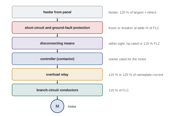
A complete motor circuit, from the panel to the motor, contains the following parts, each with its own code requirements:
- The motor feeder (where several motors share a feeder) and its overcurrent protection.
- The motor branch-circuit short-circuit and ground-fault protective device: fuses or a circuit breaker, sized to carry the starting current while protecting against faults.
- The disconnecting means for the controller and for the motor.
- The motor controller: the starter or contactor that starts and stops the motor (Lesson 6).
- The motor overload protection: usually an overload relay in the starter, sized close to the motor's running current.
- The branch-circuit conductors from the protective device to the motor.
- The motor control circuit, which operates the controller (Lessons 7 to 9).
These functions may be combined in one device, for example a combination starter containing a disconnect, fuses or breaker, contactor and overload relay in one enclosure, or a motor protective circuit breaker that provides both short-circuit and overload protection. Each function must still be satisfied.
Finding the full-load current
In Canada, Section 28 of the CEC bases conductor, overcurrent and overload sizing on the full-load current rating of the motor. This is generally the nameplate current; Tables 44 (three-phase) and 45 (single-phase) give full-load currents to use where the nameplate rating is not available, for example when designing before the motor has been selected. Typical values from Table 44 for 575 V three-phase motors are 6.1 A for 5 hp, 11 A for 10 hp, 17 A for 15 hp, 22 A for 20 hp, 27 A for 25 hp and 52 A for 50 hp. Confirm current provincial adoption and amendments before relying on a rule number.
Branch-circuit conductors
Conductors supplying a single motor used for continuous duty must have an ampacity of at least 125 % of the motor's full-load current. The extra 25 % allows for the overload relay setting, which may let the motor run at up to 125 % of its rated current indefinitely without tripping. Conductor ampacity must also be corrected for ambient temperature and adjusted for the number of current-carrying conductors in a raceway, as for any circuit, and the termination temperature ratings (usually 75 °C for equipment over 100 A or marked for it, and often 60 °C for smaller equipment unless marked otherwise) limit the ampacity that can be used. Motors with short-time or intermittent duty, such as some hoist and valve-actuator motors, use different percentages given in the code.
In the CEC, Rule 28-106 sets the 125 % requirement for conductors of a single motor, and Rule 28-108 covers conductors supplying several motors.
Short-circuit and ground-fault protection
The branch-circuit protective device must allow the motor to start and accelerate, so it is sized well above the full-load current, as a percentage that depends on the type of device. The code tables give maximum ratings for each device type:
| Device | Typical maximum rating (% of full-load current) | Notes |
|---|---|---|
| Non-time-delay fuse | 300 % | Fast fuses must ride through inrush |
| Time-delay (dual-element) fuse | 175 % | Time delay carries the inrush |
| Inverse-time circuit breaker | 250 % | Thermal-magnetic breaker |
| Instantaneous-trip breaker (motor circuit protector) | 800 % to 1,100 % or more | Only as part of a listed combination starter |
Where the calculated value does not correspond to a standard fuse or breaker size, the next larger standard size is permitted. If that size still does not allow the motor to start, the code allows a further increase within stated limits. Because this device is sized far above the conductor ampacity, it protects against short circuits and ground faults, not against overload; overload protection is the overload relay's job.
In the CEC, Rule 28-200 and Table 29 give the maximum ratings of overcurrent devices for motor branch circuits, including the permission to use the next higher standard rating.
Overload protection
Overload protection prevents motor windings and conductors from overheating when the motor carries more than its rated current for too long, whether because the driven machine is overloaded, a bearing is failing, voltage is low or unbalanced, or a phase is lost. The overload device is sized from the motor nameplate full-load current:
- Motors with a marked service factor of 1.15 or more, or a marked temperature rise of 40 °C or less: not more than 125 % of nameplate full-load current.
- All other motors: not more than 115 %.
If the motor cannot start or carry its load with these settings, the code allows the next higher setting or heater size, up to 140 % and 130 % respectively. For relays with a dial setting, the dial is usually set to the motor nameplate current, and the relay's built-in characteristic provides the margin; follow the relay manufacturer's instructions, which may require setting at the nameplate value or at the nameplate value times the service factor allowance. Overload relays and their trip classes are covered in Lesson 6.
In the CEC, Rule 28-306 sets the 125 % and 115 % limits for overload devices, and Rule 28-308 covers the number and location of overload devices (one in each ungrounded conductor for three-phase motors).
Worked example: a single motor
Worked problem
Sizing a motor branch circuit
A 25 hp, 575 V, three-phase Design B motor with SF 1.15 has a nameplate full-load current of 26 A. Size the copper conductors (75 °C terminations), the inverse-time breaker, the alternative time-delay fuses and the overload setting.
Show solution
- Full-load current for sizing: the nameplate rating, 26 A.
- Conductors: 1.25 × 26 = 32.5 A; 10 AWG copper (35 A at 75 °C, Table 2).
- Inverse-time breaker: 2.5 × 26 = 65 A; next standard size 70 A.
- Time-delay fuses: 1.75 × 26 = 45.5 A; next standard size 50 A.
- Overload: SF 1.15, so not more than 1.25 × 26 = 32.5 A.
Answer: 10 AWG copper, a 70 A inverse-time breaker (or 50 A time-delay fuses), and overload protection set at no more than 32.5 A. Notice that the breaker is twice the conductor ampacity: it protects against faults only, while the overload relay protects against overload.
Several motors on one feeder
Where a feeder supplies several motors, its conductors must carry 125 % of the full-load current of the largest motor plus 100 % of the full-load currents of all the others, plus any other loads. The feeder overcurrent device must not exceed the rating of the largest branch-circuit protective device in the group plus the sum of the full-load currents of the other motors; if this does not correspond to a standard size, the next lower standard size is used. This rule assumes that only one motor starts at a time while the others run, so that the feeder device can ride through the largest motor's start.
Worked problem
Sizing a motor feeder
A feeder supplies three 575 V motors: 25 hp (27 A), 10 hp (11 A) and 5 hp (6.1 A), using Table 44 values. The 25 hp motor is protected by a 70 A inverse-time breaker. Size the copper feeder conductors (75 °C) and the maximum feeder breaker.
Show solution
- Conductor ampacity: 1.25 × 27 + 11 + 6.1 = 50.9 A, so 6 AWG copper (65 A); 8 AWG (50 A) is just too small.
- Feeder breaker: 70 + 11 + 6.1 = 87.1 A maximum.
- The next lower standard size is 80 A.
Answer: 6 AWG copper feeder conductors protected by an 80 A breaker (CEC Rules 28-108 and 28-204).
Disconnecting means
Every motor and controller must have a disconnecting means that opens all ungrounded conductors, so that the equipment can be isolated for maintenance. The disconnect must be within sight of the controller, and generally also within sight of the motor and driven machine, so that a person working on the machine can see that it is open; within sight means visible and not more than 9 m (30 ft) away. Where a disconnect cannot be within sight of the motor, the code permits a controller disconnect that can be locked in the open position, with conditions. The disconnect must be rated in horsepower at least equal to the motor, or, for circuit breakers and molded-case switches, at least 115 % of the full-load current, and must clearly indicate whether it is open or closed.
In the CEC, Rules 28-600 to 28-604 cover the disconnecting means for motors and controllers, including the within-sight and lockable requirements and ratings.
Lockable disconnects at the motor are good practice even where not strictly required, because they let workers apply their own locks where they can see the machine.
Voltage drop and long runs
The code sets minimum conductor sizes for safety, not for performance. Voltage drop on long motor circuits reduces starting torque (with the square of voltage) and increases running current, so designers commonly limit voltage drop to about 3 % on a branch circuit and 5 % overall at full load, and check that the voltage at the motor during starting stays high enough, often at least 80 % to 85 % of rated voltage, for the motor to accelerate its load. For a three-phase circuit, voltage drop can be estimated as:
where R and X are the conductor resistance and reactance per unit length and φ is the power factor angle. During starting, the current is six or more times larger and the power factor much lower, so the starting voltage drop may be five to ten times the running drop. For long runs to large motors, larger conductors, a reduced-voltage starter or a drive may be needed (Lesson 10).
Special motor circuits
Several kinds of motor load have their own rules. Hermetic refrigerant motor-compressors in air-conditioning and refrigeration equipment are sized from the rated-load current and branch-circuit selection current marked on the equipment, and the equipment nameplate gives a minimum circuit ampacity and a maximum overcurrent protection rating that must be followed. Motors on adjustable-speed drives are supplied according to the drive's rated input current, with conductors at 125 % of that current, and the drive often provides the motor overload protection electronically (Lesson 11). Fire pump motors are deliberately not protected against overload, because keeping the pump running during a fire matters more than saving the motor, and their circuits follow special rules for supply reliability. Motors in hazardous locations must use equipment approved for the class and zone or division.
Control circuit protection
Motor control circuits, which operate the starter coils, pilot lights and relays, need their own overcurrent protection. Where the control circuit is tapped from the motor branch circuit, the control conductors are usually far smaller than the branch-circuit protective device could protect, so they need separate fuses or a control transformer with primary and secondary protection. Control transformers commonly step 480 V or 600 V down to 120 V; one side of the secondary is usually grounded, with fuses or a breaker in the ungrounded side, so that a ground fault in the control wiring blows the fuse rather than starting the motor (Lesson 8).
Common mistakes
MistakeSizing the branch breaker like an ordinary circuit and having it trip on starting.
InsteadUse the code table percentage for the protective device type.
MistakeAssuming the branch breaker protects against overload.
InsteadProvide and set overload protection separately from nameplate current.
MistakeUsing the wrong full-load current source.
InsteadUse the nameplate full-load current, or Tables 44 and 45 where it is not available.
MistakeRounding the feeder breaker up.
InsteadFor motor feeders, use the next lower standard size.
MistakePlacing the motor disconnect out of sight of the machine.
InsteadLocate it within sight, or use a permitted lockable controller disconnect.
Summary and key terms
- Motor circuits separate short-circuit and ground-fault protection from overload protection.
- The CEC sizes motor circuits from the full-load current rating, generally the nameplate, with Tables 44 and 45 where needed.
- Single-motor conductors are sized at 125 % of full-load current.
- Short-circuit protective devices are sized at table percentages, such as 250 % for inverse-time breakers.
- Overloads are set at no more than 125 % (SF 1.15 or more) or 115 % of nameplate current.
- Feeders carry 125 % of the largest motor plus the others; feeder protection rounds down.
- Disconnects must be within sight, rated in horsepower or 115 % of full-load current.
- Motor branch circuit
- The circuit from the protective device to a motor.
- Short-circuit and ground-fault protection
- Fuses or breakers sized to clear faults while allowing starting.
- Overload protection
- A device that trips on sustained overcurrent to protect the motor.
- Full-load current
- Current at rated load, from the nameplate or code tables.
- Inverse-time breaker
- A thermal-magnetic breaker that trips faster at higher overcurrent.
- Time-delay fuse
- A fuse that withstands short overloads such as motor starting.
- Motor circuit protector
- An instantaneous-trip breaker used in listed combination starters.
- Combination starter
- An enclosure with disconnect, protection, contactor and overload relay.
- Within sight
- Visible and not more than 9 m (30 ft) away.
- Control transformer
- A transformer supplying a low-voltage control circuit.
Practice problems
Work each problem on paper first, then reveal the answer to check.
Why does a motor branch circuit need two kinds of protection?
Show answer
A device that allows starting current cannot also protect against overload, so an overload relay is added.
What ampacity must conductors to a single continuous-duty motor have?
Show answer
At least 125 % of full-load current.
What is the maximum inverse-time breaker for a motor with 40 A full-load current?
Show answer
2.5 × 40 = 100 A.
What time-delay fuse size corresponds to 20 A full-load current?
Show answer
1.75 × 20 = 35 A.
A motor without a marked service factor has nameplate current 18 A. What is the maximum overload setting?
Show answer
1.15 × 18 = 20.7 A.
If the overload trips during normal starting, what does the code allow?
Show answer
Increasing to not more than 140 % (or 130 %) of nameplate current.
Size feeder conductors for motors with full-load currents of 40 A, 20 A and 10 A.
Show answer
1.25 × 40 + 20 + 10 = 80 A.
For motor feeders, does the protective device round up or down?
Show answer
Down, to the next lower standard size.
What does "within sight" mean?
Show answer
Visible and not more than 9 m (30 ft) away.
Why are fire pump motors not protected against overload?
Show answer
Keeping the pump running during a fire matters more than protecting the motor.
Lesson quiz · 5 questions
Score 60% or more to complete this lesson.
Create a free account to save your progress, take quizzes and earn a certificate.