
ELEC-310 · Lesson 4 of 12 · 29 min
Motor installation, connections and alignment
A motor that is well chosen and correctly protected can still fail early if it is installed badly. Misalignment wears out bearings and couplings, a loose foundation causes vibration, wrong lead connections burn out windings within minutes, and moisture absorbed during storage can break down insulation on the first start. Many motor failures that end up in the repair shop began at installation. This lesson follows a motor from delivery to first run: receiving and storage, mounting and foundations, terminal markings and connections for single- and dual-voltage motors, conductor terminations in the terminal box, insulation and winding tests before start-up, shaft alignment and belt drives, lubrication, and the first run.
Receiving and storage
When a motor arrives, check it against the order and the drawings: horsepower, voltage, speed, frame, enclosure, mounting and shaft dimensions. Inspect for shipping damage, turn the shaft by hand to confirm it rotates freely, and note any shaft locking device fitted for shipping, which must be removed before running. If the motor will not be installed immediately, store it indoors in a clean, dry place with a stable temperature. Motors in storage absorb moisture, particularly in unheated buildings where temperature swings cause condensation, and bearings can suffer false brinelling (dents in the races) from vibration transmitted through the floor while the shaft is stationary. Good practice is to rotate the shaft several turns every month, energize space heaters if fitted, and measure insulation resistance before installation. Large motors stored for long periods may need their bearings regreased or inspected.
Mounting and foundations
A motor must be mounted on a rigid, level base that will not flex or resonate. Large motors sit on steel bases grouted to concrete foundations with a mass several times that of the machine; smaller motors may mount on fabricated steel bases or directly on the driven machine. Bolts must be of the correct grade and torqued to specification, and shims used for levelling and alignment should be stainless-steel precut shims of the correct size, as few as possible (no more than three or four under any foot), and clean.
Before final alignment, check for soft foot: a condition where one or more feet do not sit flat on the base, so that tightening the hold-down bolts distorts the motor frame. Soft foot distorts the bearing housings and stator, causing vibration, bearing wear and, in severe cases, rubbing between rotor and stator. To check, tighten all bolts, then loosen one at a time with a dial indicator on the foot; movement of more than about 0.002 in (0.05 mm) indicates soft foot, which is corrected with shims under that foot.
Terminal markings
Motor leads are marked so that they can be connected correctly. NEMA marks three-phase stator leads T1 to T12, single-phase leads T1 to T8 (main winding T1 to T4, auxiliary T5 to T8), and DC motor leads A1 and A2 (armature), F1 and F2 (shunt field) and S1 and S2 (series field). IEC marks three-phase winding ends U1, V1, W1 and U2, V2, W2. The connection diagram on the nameplate or inside the terminal box cover is the authority for a particular motor; never assume.
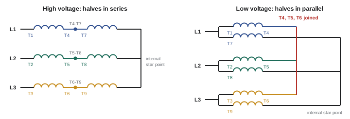
A single-voltage three-phase motor has three leads, T1, T2 and T3, connected to L1, L2 and L3. A dual-voltage motor, commonly 230/460 V, has each phase winding split into two equal halves. For the high voltage, the halves of each phase are connected in series; for the low voltage, in parallel. The two common arrangements bring out nine leads:
| Connection | Low voltage (parallel) | High voltage (series) |
|---|---|---|
| 9-lead wye | L1: T1, T7; L2: T2, T8; L3: T3, T9; join T4, T5, T6 | L1: T1; L2: T2; L3: T3; join T4-T7, T5-T8, T6-T9 |
| 9-lead delta | L1: T1, T6, T7; L2: T2, T4, T8; L3: T3, T5, T9 | L1: T1; L2: T2; L3: T3; join T4-T7, T5-T8, T6-T9 |
In the 9-lead wye motor, T4, T5 and T6 form the internal star point when connected for low voltage. Notice that the high-voltage connections are the same for both winding types. Twelve-lead motors bring out both ends of every winding half, allowing wye or delta connection at either voltage, which is used for wye-delta starting (Lesson 10).
Worked problem
Identifying a mistake in a dual-voltage connection
A 230/460 V, 9-lead wye motor is connected to a 460 V supply with L1 on T1 and T7, L2 on T2 and T8, L3 on T3 and T9, and T4, T5 and T6 joined. What will happen, and what is the correct connection?
Show solution
- This is the low-voltage (parallel) connection: each winding half sees the voltage intended for the whole series pair.
- Each winding half receives twice its rated voltage, so magnetizing current rises enormously as the iron saturates.
- The motor will draw very high current and trip its protection, or burn out within seconds to minutes if protection is wrong.
- Correct connection for 460 V: L1 to T1, L2 to T2, L3 to T3, and join T4 to T7, T5 to T8 and T6 to T9, each joint insulated.
Answer: The motor is connected for 230 V on a 460 V supply and will be destroyed if it runs. Always compare the supply voltage with the connection diagram before energizing, and label the terminal box with the voltage it is connected for.
Terminations in the terminal box
Connections in the terminal box must be mechanically secure and well insulated, because motor vibration loosens poor joints. Common methods are bolted lug-to-lug connections with ring terminals, insulated with motor lead tape systems or heat-shrink boots; split-bolt connectors; and terminal blocks fitted in some motors. Twist-on wire connectors are used only on small motors and only where listed for the conductor sizes and the vibration involved. Crimp lugs must suit the conductor and be crimped with the matching die. Bolted connections should be torqued to the specified value, and joints should be arranged so that they do not press against the box or cover.
The supply raceway or cable should enter the terminal box through a fitting that keeps out dust and water, and the final length to the motor is usually liquidtight flexible metal conduit or a flexible cable, to absorb vibration and allow for belt adjustment. The motor frame must be bonded to the equipment grounding conductor, which is terminated on the grounding lug inside the terminal box; flexible conduit should not be relied on as the only bonding path for motors. On drive-fed motors, symmetrical shielded VFD cable with its shield bonded at both ends, or a separate bonding conductor sized to the drive manufacturer's recommendations, helps control high-frequency currents (Lesson 11).
Testing before start-up
Before energizing a new, repaired or long-stored motor, test its windings:
- Insulation resistance: apply a DC test voltage between the windings (all leads connected together) and the frame with an insulation resistance tester (megohmmeter), typically 500 V for motors rated up to 600 V and 1,000 V for motors rated up to 1,000 V. Following IEEE 43, the reading after one minute, corrected to 40 °C, should be at least 5 MΩ for random-wound motors rated below 1 kV; most healthy motors read hundreds or thousands of megohms. Disconnect drives, surge capacitors and other electronics first, because the test voltage can damage them.
- Polarization index (PI): the ratio of the 10-minute reading to the 1-minute reading. Clean, dry insulation shows rising resistance as the dielectric polarizes; a PI of 2.0 or more is generally acceptable for Class B and higher insulation, while a PI near 1 suggests moisture or contamination.
- Winding resistance: measure the resistance of each phase (or between each pair of leads) with a low-resistance ohmmeter. The readings should agree within a few percent; a larger difference suggests a shorted turn, a poor connection or an incorrect internal connection.
Insulation resistance falls roughly by half for every 10 °C rise in temperature, so readings should be corrected to a common temperature, usually 40 °C, before comparison with earlier tests. A low reading on a stored motor is often caused by moisture and can be corrected by drying with space heaters, a low-voltage current through the windings, or an oven at a repair shop, before the motor is energized.
Worked problem
Interpreting insulation tests
A 460 V motor that has been stored in an unheated building reads 3.5 MΩ after 1 minute and 4.0 MΩ after 10 minutes at 500 V DC, with the winding at 20 °C. Should it be started?
Show solution
- Correct the 1-minute reading to 40 °C: halving for each 10 °C rise gives 3.5 ÷ 4 = 0.9 MΩ.
- The corrected value is far below the 5 MΩ minimum.
- PI = 4.0 ÷ 3.5 = 1.14, well below 2.0, consistent with moisture.
Answer: Do not start the motor. Dry the windings, for example with space heaters or a controlled low-voltage current, and retest until both the corrected insulation resistance and the PI are acceptable.
Shaft alignment
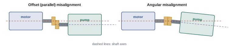
When a motor drives a machine through a flexible coupling, the motor and machine shafts must be aligned so that their centrelines are collinear when the machines are at operating temperature. Misalignment has two components: offset (parallel) misalignment, where the centrelines are parallel but displaced, and angular misalignment, where the centrelines meet at an angle. Both occur in the vertical and horizontal planes. Misalignment causes vibration, heat in the coupling, and excessive loads on bearings and seals; it is one of the most common causes of bearing failure. Flexible couplings accommodate small misalignment, but their tolerance is for the coupling's survival, not the bearings'.
Alignment methods include, in increasing order of accuracy:
- Straightedge and feeler gauge: quick, but only adequate for low-speed, small machines.
- Dial indicators: in the rim-and-face method, one indicator reads the rim (offset) and another the face (angularity) of the coupling as the shafts are rotated together; the reverse-dial method reads the rim of each shaft from the other, and is more accurate for long couplings.
- Laser alignment systems: emitter and detector units clamp to the shafts, and software calculates the shim changes and horizontal moves needed at each motor foot. Laser systems are fast, accurate and now standard practice in industry.
Alignment tolerances depend on speed: for a 1,800 rpm machine, typical acceptable tolerances are about 0.004 in (0.10 mm) of offset and 0.0005 in per inch (0.05 mm per 100 mm) of angularity, with tighter values for 3,600 rpm machines. Allow for thermal growth: a motor and a hot pump may grow by different amounts as they warm up, so the cold alignment is set with a deliberate offset that disappears at operating temperature, as given by the equipment manufacturer.
Belt drives
V-belt and synchronous belt drives allow the driven speed to differ from the motor speed. The speed ratio is the inverse of the pulley (sheave) diameter ratio:
For example, a 1,760 rpm motor with a 5 in sheave driving a 10 in sheave turns the fan at 880 rpm. On a fan or pump, a larger motor sheave increases speed and therefore power with the cube of speed, which can overload the motor; any sheave change should be checked against the motor's full-load current.
Belt drives must be aligned so that the sheave faces are in the same plane; a straightedge or laser line across both faces checks this. Belt tension should follow the manufacturer's method, often a specified deflection force at the middle of the span (a common rule is 1/64 in deflection per inch of span, or about 1.6 mm per 100 mm) measured with a tension gauge. Overtightened belts overload motor bearings and shafts; loose belts slip, squeal, wear and heat. Matched sets of belts should be replaced together, and guards must be reinstalled before running.
Bearings and lubrication
Most motors use ball bearings, with roller bearings on the drive end of larger belted motors and sleeve bearings on some large machines. Sealed bearings are lubricated for life; regreasable bearings need the correct grease, in the correct amount, at the correct interval given by the manufacturer. Over-greasing is a more common fault than under-greasing: excess grease is churned, heats the bearing and can be forced into the windings. A good practice is to wipe the fittings, remove the drain plug, add grease slowly with the motor running if safe to do so (or as the manufacturer directs), and leave the drain open until excess grease stops purging. Different grease types can be incompatible, so mixing them should be avoided. Bearing condition is monitored by vibration analysis, temperature and ultrasound (Lesson 12).
The first run
Before the first start, confirm that the lockout has been removed by the people who applied it, that the motor and driven machine are clear of tools and people, that guards are in place, that the voltage at the starter matches the motor connection, and that overload settings are correct (Lesson 6). Bump the motor to check rotation, with the coupling disconnected if reverse rotation could damage the load. Then run the motor, measure the current in all three phases (it should be balanced and below nameplate full-load current at normal load), measure the voltage at the terminals, listen for unusual noise, and check bearing temperature and vibration after the motor has stabilized. Record the readings as a baseline for future maintenance.
Common mistakes
MistakeEnergizing a dual-voltage motor without checking its connection.
InsteadCompare the supply voltage with the terminal connections every time.
MistakeStarting a stored motor without testing insulation.
InsteadMeasure insulation resistance and PI, correcting for temperature.
MistakeLeaving soft foot uncorrected.
InsteadCheck each foot with a dial indicator and shim before aligning.
MistakeRelying on a flexible coupling to absorb misalignment.
InsteadAlign to the speed-based tolerance, allowing for thermal growth.
MistakeOver-greasing bearings.
InsteadAdd the specified quantity at the specified interval and let excess purge.
Summary and key terms
- Inspect motors on arrival and store them clean, dry and with shafts rotated periodically.
- Mount motors rigidly and correct soft foot before alignment.
- NEMA leads are T1 to T12; dual-voltage windings are in series for high voltage and parallel for low.
- Terminations must be secure, insulated and bonded, with flexible connections for vibration.
- Test insulation resistance, PI and winding balance before start-up.
- Align shafts for offset and angularity within speed-based tolerances; tension and align belts correctly.
- Grease bearings correctly, then check rotation, current, voltage, noise and vibration on the first run.
- Soft foot
- A motor foot that does not sit flat, distorting the frame when bolted.
- Dual-voltage motor
- A motor whose winding halves connect in series or parallel for two voltages.
- Insulation resistance
- Resistance between windings and frame measured with a DC test voltage.
- Polarization index
- Ratio of 10-minute to 1-minute insulation resistance.
- Offset misalignment
- Parallel but displaced shaft centrelines.
- Angular misalignment
- Shaft centrelines meeting at an angle.
- Laser alignment
- Shaft alignment using laser emitters, detectors and software.
- Thermal growth
- Change in shaft height as machines reach operating temperature.
- Sheave
- A grooved pulley for V-belts.
- False brinelling
- Bearing race damage from vibration while stationary.
Practice problems
Work each problem on paper first, then reveal the answer to check.
Why should a stored motor's shaft be rotated periodically?
Show answer
To prevent false brinelling and redistribute bearing grease.
How much foot movement indicates soft foot?
Show answer
More than about 0.002 in (0.05 mm).
For a 9-lead wye motor on 460 V, which leads are joined?
Show answer
T4-T7, T5-T8 and T6-T9.
For the same motor on 230 V, which leads are joined together?
Show answer
T4, T5 and T6, with T1-T7, T2-T8 and T3-T9 on the lines.
What test voltage is typical for insulation testing a 460 V motor?
Show answer
500 V DC (up to 1,000 V).
A reading of 40 MΩ at 30 °C corresponds to what at 40 °C?
Show answer
About 20 MΩ.
What PI is generally acceptable for Class B and higher insulation?
Show answer
2.0 or more.
A 1,750 rpm motor with a 6 in sheave drives an 8 in sheave. What is the driven speed?
Show answer
1,750 × 6 ÷ 8 = 1,313 rpm.
Why is cold alignment sometimes set with a deliberate offset?
Show answer
To allow for different thermal growth so shafts align when hot.
Name four readings to take on the first run.
Show answer
Phase currents, terminal voltage, noise, bearing temperature, vibration.
Lesson quiz · 5 questions
Score 60% or more to complete this lesson.
Create a free account to save your progress, take quizzes and earn a certificate.