
ELE-470 · Lesson 7 of 12 · 31 min
Inverters
An inverter converts DC into AC of controlled voltage and frequency. Inverters connect solar panels and batteries to the grid, drive motors at variable speed (Lesson 9), produce clean AC in uninterruptible power supplies, power electric vehicles, and form the converter stations of modern HVDC links. This lesson builds up from the basic switching leg to single-phase and three-phase bridges, explains pulse-width modulation and its harmonic spectrum, introduces multilevel inverters and output filters, and covers two applications central to energy and data centre engineering: grid-connected inverters and UPS systems.
The switching leg
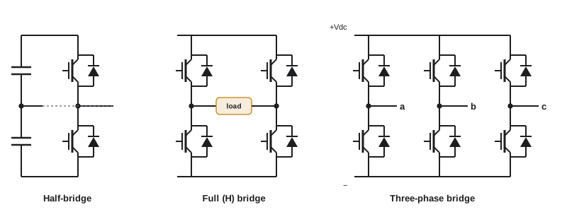
The building block of most inverters is a leg (or phase leg): two switches in series across the DC bus, each with an anti-parallel diode, with the output taken from the midpoint. Turning on the upper switch connects the output to \(+V_{dc}/2\) (measured from the DC midpoint); turning on the lower switch connects it to \(-V_{dc}/2\). The diodes allow current to flow in either direction regardless of which switch is on, which is essential with inductive loads. Dead time between the two gate signals prevents shoot-through (Lesson 1).
A half-bridge inverter is one leg with a split DC capacitor; its output swings between \(\pm V_{dc}/2\). A full-bridge (H-bridge) inverter uses two legs with the load between their midpoints, so the output can be \(+V_{dc}\), \(0\) or \(-V_{dc}\). A three-phase inverter uses three legs, one per phase.
Square-wave operation
The simplest control turns each leg's switches on for half the output period, producing a square wave. A square wave of amplitude \(V_{dc}/2\) has a fundamental of peak value \(\frac{4}{\pi} \cdot \frac{V_{dc}}{2}\) and odd harmonics with amplitudes falling as \(1/h\). Square-wave operation gives the maximum possible fundamental voltage and the lowest switching loss, but its voltage cannot be controlled except by varying \(V_{dc}\), and its large low-order harmonics (3rd, 5th, 7th) cause losses and torque ripple in motors. It is used in some high-power traction drives at top speed and in low-cost converters.
Sinusoidal pulse-width modulation
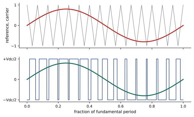
Pulse-width modulation (PWM) switches each leg at a high frequency and varies the duty cycle so that the average output over each switching period follows a sinusoidal reference. In sine-triangle PWM, a sinusoidal reference of amplitude \(m\) (the modulation index) is compared with a triangular carrier of amplitude 1 at the switching frequency; the upper switch is on whenever the reference exceeds the carrier. For \(0 \le m \le 1\) (linear modulation), the fundamental of each leg voltage has peak \(m\, V_{dc}/2\), and for a three-phase inverter the rms line-to-line fundamental is:
The harmonics are moved to frequencies around the switching frequency and its multiples, where they are easily filtered by the inductance of a motor or an output filter. The ratio of carrier to fundamental frequency is the frequency modulation ratio \(m_f\).
import numpy as np

Vdc, f1, mf = 650.0, 60.0, 39
N = 200000
t = np.arange(N) / (N * f1)
tri = 2 * np.abs(2 * ((t * f1 * mf) % 1) - 1) - 1


def leg(ref):
    return np.where(ref >= tri, Vdc / 2, -Vdc / 2)


for m, inject in [(0.8, False), (1.0, False), (1.15, True), (1.3, False)]:
    refs = [m * np.sin(2 * np.pi * f1 * t - k * 2 * np.pi / 3) for k in range(3)]
    if inject:
        third = m / 6 * np.sin(3 * 2 * np.pi * f1 * t)
        refs = [r + third for r in refs]
    va, vb = leg(refs[0]), leg(refs[1])
    vab = va - vb
    spec = np.abs(np.fft.rfft(vab)) * 2 / N / np.sqrt(2)
    fund = spec[1]
    thd = np.sqrt(np.sum(spec[2:]**2)) / fund
    low = np.sqrt(np.sum(spec[2:20] ** 2)) / fund
    tag = " with third-harmonic injection" if inject else ""
print(f"m = {m:.2f}{tag}: VLL fundamental {fund:6.1f} V rms (linear theory {0.612 * m * Vdc:6.1f}) THD {100 * thd:5.1f}% low-order {100 * low:4.1f}%")m = 0.80: VLL fundamental 318.4 V rms (linear theory 318.2) THD 91.5% low-order 0.0% m = 1.00: VLL fundamental 398.0 V rms (linear theory 397.8) THD 68.6% low-order 0.0% m = 1.15 with third-harmonic injection: VLL fundamental 457.8 V rms (linear theory 457.5) THD 52.8% low-order 0.0% m = 1.30: VLL fundamental 451.1 V rms (linear theory 517.1) THD 55.4% low-order 3.5%
The results show three regimes. In the linear range, the fundamental equals the theory exactly and there are no low-order harmonics; the high THD consists of harmonics near the carrier frequency, which the load inductance filters. Adding a third harmonic to all three references (which cancels in the line-to-line voltage) extends the linear range to \(m = 2/\sqrt{3} \approx 1.155\), giving 15.5% more output voltage from the same DC bus; space vector modulation, commonly used in digital controllers, achieves the same result. Beyond that, overmodulation increases the fundamental only slightly and introduces low-order harmonics.
Worked problem
DC bus needed for a motor
A drive must supply 600 V line-to-line rms to a motor. What minimum DC bus voltage is needed with sine-triangle PWM (m = 1) and with space vector modulation?
Show solution
- Sine-triangle: \(V_{dc} = 600/0.612 = 980\) V.
- Space vector (\(m = 1.155\)): \(V_{dc} = 980/1.155 = 849\) V.
Answer: About 980 V with sine-triangle PWM but only 849 V with space vector modulation, which equals the peak line voltage that a diode rectifier on a 600 V supply provides. This is why drives use space vector or third-harmonic modulation: they can give full motor voltage from a simple rectifier.
Real inverters deviate from ideal PWM in one important way: the dead time inserted between the two switches of each leg. During the dead time, the output voltage is set by whichever diode carries the load current, so each switching period loses or gains a small volt-second area depending on the current direction. The result is a voltage error proportional to the dead time multiplied by the switching frequency, which distorts the output near current zero crossings and reduces voltage at low speeds. Drives measure the current direction and add compensating pulses to cancel most of this effect.
Multilevel inverters
A two-level inverter switches each output between two voltages, so every transition is a full \(V_{dc}\) step. Multilevel inverters synthesize the output from more levels, giving smaller steps, lower harmonics, lower \(dv/dt\) and the ability to use lower-voltage devices for higher total voltage. Common types are:
- Neutral-point-clamped (NPC) three-level inverters, with four switches and two clamping diodes per leg, widely used in medium-voltage drives, solar inverters and high-efficiency UPS systems.
- Flying capacitor inverters, which use capacitors to create intermediate levels.
- Cascaded H-bridge inverters, with several H-bridge cells in series per phase, each with its own isolated DC source, used in medium-voltage drives and static compensators.
- Modular multilevel converters (MMC), with hundreds of submodules per arm, now the standard topology for voltage-source HVDC links.
Worked problem
Levels and step size
An HVDC MMC operates at ±320 kV DC, with each arm made of submodules rated about 1.6 kV. How many submodules are needed per arm, and what is the voltage step?
Show solution
- Each arm must withstand the full pole-to-pole voltage: \(640/1.6 = 400\) submodules (before redundancy).
- Voltage step: about 1.6 kV, compared with 640 kV for a hypothetical two-level converter.
Answer: About 400 submodules per arm plus redundant spares, producing a staircase output so fine that little or no filtering is needed and switching frequency per device can be low, giving efficiencies around 99%.
Output filters
Motor loads filter PWM harmonics with their own inductance, although fast edges cause other problems (Lesson 9). Grid-connected inverters and UPS outputs need explicit filters: an L filter (a series inductor), an LC filter for voltage-source outputs such as UPS, or an LCL filter for grid connection, which attenuates switching harmonics much more strongly with smaller components but has a resonance that must be damped passively or by the control. Filter design balances attenuation of switching-frequency ripple, size and cost, reactive current drawn by capacitors, and control bandwidth.
Grid-connected inverters
Solar, wind (through full or partial converters), battery storage and fuel cells connect to the grid through inverters. A grid-following inverter measures the grid voltage, tracks its phase with a phase-locked loop (PLL), and controls its output current to inject the desired active and reactive power. Grid-forming inverters instead behave like voltage sources that set their own voltage and frequency, sharing load through droop control; they can support weak grids and island operation and are increasingly required as inverter-based resources replace synchronous generators.
Interconnection standards specify how inverters must behave: voltage and frequency ranges, ride-through of disturbances rather than tripping, reactive power and voltage regulation functions, frequency response, power quality, and anti-islanding protection (detecting loss of the utility and stopping within about 2 seconds so that utility workers are not endangered by an energized island).
In Canada, distributed resources connecting to distribution systems follow CSA C22.3 No. 9 (Interconnection of distributed energy resources and electricity supply systems) and the requirements of the local utility; inverters are certified to CSA C22.2 No. 107.1 (and often UL 1741 as well). Some utilities have adopted requirements based on IEEE 1547-2018 for ride-through and grid support functions.
Worked problem
Inverter current and power
A 100 kW three-phase solar inverter connects to a 600 V system and must be able to supply reactive power at 0.9 power factor at full active power. What apparent power rating and current are needed?
Show solution
- Apparent power: \(S = 100/0.9 = 111\) kVA; reactive power \(Q = \sqrt{111^2 - 100^2} = 48.4\) kvar.
- Current: \(I = 111000/(\sqrt{3} \times 600) = 107\) A.
Answer: A rating of about 111 kVA and 107 A. Requiring reactive capability at full output means oversizing the inverter by about 11%.
Uninterruptible power supplies
A UPS keeps critical loads running through utility disturbances and outages until generators start or the load shuts down safely. IEC 62040-3 classifies UPS by how the output depends on the input:
- Passive standby (offline): the load is normally fed from the utility; on failure, a switch transfers it to an inverter running from batteries. Cheap, but with a transfer gap of a few milliseconds and no conditioning; used for small loads.
- Line interactive: an inverter connected in parallel with the line regulates voltage and charges batteries; it takes over during failures. Used up to a few kilovolt-amperes and in some larger designs.
- Double conversion (online): a rectifier converts AC to DC, feeding batteries and an inverter that continuously supplies the load. The output is fully regenerated and isolated from input disturbances, with no transfer time. This is the standard for data centres.
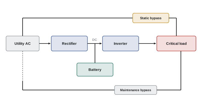
Double conversion costs efficiency because every watt passes through two converters. Modern transformerless UPS designs with three-level IGBT or SiC inverters reach 96% to 97.5%. Eco modes run the load on the bypass during normal conditions, with the inverter ready to take over within milliseconds, reaching 99% efficiency; advanced modes keep the inverter connected to compensate harmonics and reactive power while the bypass carries the real power. Operators weigh the energy savings against the small risk of exposing loads to utility disturbances.
Worked problem
Value of UPS efficiency
A data centre has 10 MW of IT load on UPS systems running continuously. Compare annual losses at 96% efficiency (double conversion) and 99% (eco mode), and the cost at $0.08/kWh, including cooling that requires 0.3 kW per kW of heat.
Show solution
- 96%: losses \(= 10/0.96 - 10 = 0.417\) MW. 99%: \(10/0.99 - 10 = 0.101\) MW. Difference 0.316 MW.
- With cooling: \(0.316 \times 1.3 = 0.41\) MW; annual energy \(0.41 \times 8760 = 3600\) MWh.
- Cost: \(3.6 \times 10^{6} \times 0.08 = \$288{,}000\) per year.
Answer: About 3,600 MWh and $288,000 a year, which explains the interest in high-efficiency UPS modes and topologies. UPS systems are certified to safety standards such as UL 1778 or CSA C22.2 No. 107.3 and are covered in more depth in DCE-340.
Lesson 10 applies inverters to solar, wind, storage and vehicle charging, and Lesson 11 scales the same principles up to HVDC and FACTS converters in the transmission grid.
Common mistakes
MistakeExpecting full motor voltage from sine-triangle PWM on a rectified bus.
InsteadUse space vector or third-harmonic injection for 15.5% more voltage.
MistakeReading high PWM THD as poor quality.
InsteadCheck where harmonics lie; high-frequency harmonics are easily filtered.
MistakeIgnoring LCL filter resonance.
InsteadDamp it passively or through control.
MistakeSizing a grid inverter only for active power.
InsteadInclude reactive power capability required by interconnection rules.
MistakeAssuming eco mode has no trade-off.
InsteadIt exposes loads briefly to utility disturbances; assess the risk.
Summary and key terms
- Inverters are built from switching legs with anti-parallel diodes and dead time.
- Square waves maximize voltage but have large low-order harmonics.
- Sine-triangle PWM gives V_LL1 = 0.612 m V_dc and pushes harmonics near the carrier.
- Third-harmonic injection or space vector modulation extends the linear range by 15.5%.
- Multilevel inverters (NPC, cascaded, MMC) reduce harmonics and dv/dt at high voltage.
- Grid inverters use PLLs and current control; interconnection standards require ride-through and anti-islanding.
- Double-conversion UPS regenerates power continuously; eco modes trade some protection for efficiency.
- Inverter
- A converter from DC to AC.
- Phase leg
- Two series switches with the output at their midpoint.
- Modulation index
- The ratio of reference amplitude to carrier amplitude in PWM.
- Space vector modulation
- A digital PWM method that maximizes linear output voltage.
- Multilevel inverter
- An inverter producing more than two voltage levels per phase.
- LCL filter
- An inductor-capacitor-inductor output filter for grid inverters.
- Phase-locked loop
- A control loop tracking the grid voltage phase.
- Grid-forming inverter
- An inverter that sets voltage and frequency like a synchronous source.
- Anti-islanding
- Detection of utility loss and shutdown of distributed generation.
- Double-conversion UPS
- A UPS supplying the load continuously through rectifier and inverter.
Practice problems
Work each problem on paper first, then reveal the answer to check.
Output voltage levels of a full H-bridge?
Show answer
+V_dc, 0 and −V_dc.
Fundamental peak of a half-bridge square wave with V_dc = 400 V?
Show answer
(4/π)(200) = 255 V.
Three-phase PWM, V_dc = 700 V, m = 0.9. Line-to-line fundamental?
Show answer
0.612 × 0.9 × 700 = 386 V rms.
Maximum linear modulation index with third-harmonic injection?
Show answer
2/√3 ≈ 1.155.
Carrier 6 kHz, fundamental 60 Hz. Frequency modulation ratio?
Show answer
100.
Name two advantages of multilevel inverters.
Show answer
Lower harmonics and dv/dt; higher voltage with lower-rated devices.
LCL filter: L1 = L2 = 1 mH, C = 20 µF. Resonant frequency?
Show answer
(1/2π)√(2e-3/(1e-6 × 2e-5)) = 1.59 kHz.
What does anti-islanding protection do?
Show answer
Stops the inverter when the utility is lost so lines are not energized.
250 kW inverter at 0.95 PF capability. kVA rating?
Show answer
263 kVA.
UPS at 97% supplying 2 MW. Losses?
Show answer
61.9 kW.
Lesson quiz · 5 questions
Score 60% or more to complete this lesson.
Create a free account to save your progress, take quizzes and earn a certificate.