
ELE-470 · Lesson 3 of 12 · 28 min
Rectifiers
A rectifier converts AC to DC. Rectifiers are the input stage of nearly every electronic load connected to the grid (computers, LED lighting, battery chargers, motor drives, UPS systems), and of high-power applications such as electrochemical plants, electric arc furnaces and HVDC terminals. The simplest rectifiers use diodes and draw current from the supply in short pulses or blocks, distorting the current waveform and creating harmonics that load the electrical system and can disturb other equipment. This lesson examines single-phase and three-phase rectifiers, both uncontrolled and thyristor-controlled, quantifies their harmonics, and explains the techniques used to reduce them, from line reactors and multipulse transformers to active power factor correction.
Single-phase rectifiers
A half-wave rectifier uses one diode to pass only the positive half-cycles; it is rarely used for power because its output has large ripple and it draws DC current from the supply. A full-wave bridge uses four diodes so that both half-cycles produce positive output. For a resistive load, the average output voltage of a bridge is:
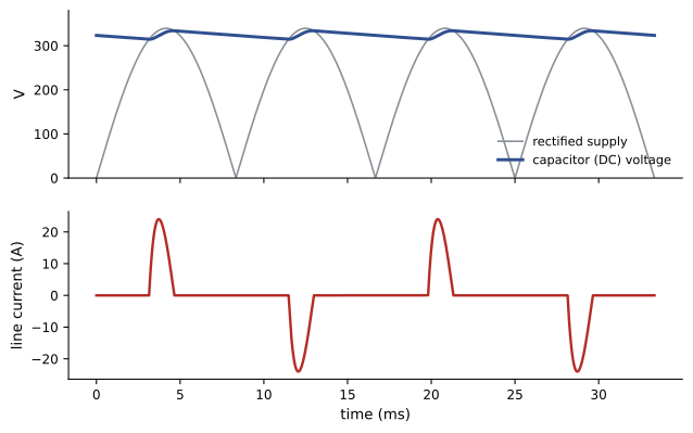
Most electronic loads place a large capacitor across the bridge output to smooth the DC. The capacitor charges to nearly the peak of the AC voltage \(\sqrt{2} V_{rms}\), and the diodes conduct only for a short interval near each voltage peak, when the supply voltage exceeds the capacitor voltage. Between peaks, the capacitor supplies the load and its voltage droops. For a load current \(I_{dc}\), the peak-to-peak ripple is approximately:
where \(f\) is the supply frequency (the factor 2 because a bridge recharges the capacitor twice per cycle).
import numpy as np

Vrms, f, Rs, C, R = 240.0, 60.0, 0.5, 1000e-6, 115.0
dt = 1e-6
t = np.arange(0, 0.2, dt)
vs = np.sqrt(2) * Vrms * np.sin(2 * np.pi * f * t)
vc = np.zeros_like(t)
i_line = np.zeros_like(t)
v = 0.0
for k in range(1, t.size):
    i = max(abs(vs[k]) - v, 0.0) / Rs
    v += (i - v / R) / C * dt
    vc[k] = v
    i_line[k] = i * np.sign(vs[k])
last = t >= 0.2 - 1 / f
v_last, i_last = vc[last], i_line[last]
p_out = np.mean(v_last ** 2) / R
i_rms = np.sqrt(np.mean(i_last ** 2))
pf = np.mean(vs[last] * i_last) / (Vrms * i_rms)
print(f"DC voltage: mean {v_last.mean():.1f} V, ripple {np.ptp(v_last):.1f} V peak to peak")
print(f"output power {p_out:.0f} W")
print(f"line current: rms {i_rms:.2f} A, peak {np.abs(i_last).max():.1f} A, crest factor {np.abs(i_last).max() / i_rms:.2f}")
print(f"conduction per half cycle: {np.mean(np.abs(i_last) > 0.01) * 100:.0f}% of the time,  power factor {pf:.2f}")
print(f"estimate dV = I/(2fC) = {v_last.mean() / R / (2 * f * C):.1f} V")DC voltage: mean 324.4 V, ripple 19.4 V peak to peak output power 915 W line current: rms 7.33 A, peak 24.0 A, crest factor 3.28 conduction per half cycle: 18% of the time, power factor 0.54 estimate dV = I/(2fC) = 23.5 V
The simulation shows the characteristic behaviour of capacitor-input rectifiers: the line current flows in narrow pulses with a crest factor above 3, and the power factor is only about 0.5 to 0.6 even though the current pulses are in phase with the voltage peaks. The low power factor is caused almost entirely by distortion, not by phase shift. The simple ripple formula overestimates the ripple somewhat because the capacitor is also recharged during part of the conduction interval.
Power factor and distortion
For non-sinusoidal currents, power factor has two components. The displacement factor \(\cos\phi_1\) reflects the phase shift between the voltage and the fundamental component of current. The distortion factor reflects the fact that harmonic currents carry no average power with a sinusoidal voltage but still add to the rms current:
Total harmonic distortion (THD) of current is the rms of all harmonic components divided by the fundamental. Capacitors used to correct displacement power factor do nothing for distortion and can even resonate with the supply inductance at a harmonic frequency, amplifying harmonics.
Single-phase rectifiers produce large third harmonic currents (and other odd triplen harmonics, 9th, 15th, and so on). In a three-phase four-wire system, triplen currents from the three phases are in phase and add in the neutral instead of cancelling, so a building full of computer loads can have neutral current larger than phase current. This is why data centres and offices use oversized neutrals or harmonic-mitigating transformers, and why modern server power supplies include active power factor correction.
Worked problem
Neutral current from triplen harmonics
Each phase of a 208Y/120 V panel supplies 60 A rms of single-phase rectifier load whose current contains a fundamental of 40 A and a third harmonic of 32 A (plus smaller harmonics). Estimate the neutral current.
Show solution
- Fundamental currents are balanced and cancel in the neutral.
- Third harmonics are in phase in all three phases: neutral third-harmonic current \(= 3 \times 32 = 96\) A.
Answer: About 96 A, 60% more than each phase current, before adding the 9th and other triplens. A neutral sized only for the phase current would overheat. Modern equipment with active PFC largely eliminates this problem, but older or low-cost loads can still cause it.
Three-phase diode bridges
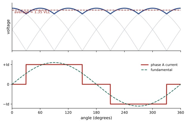
A three-phase six-pulse bridge uses six diodes, two per phase. At each instant, the diode connected to the most positive phase and the diode connected to the most negative phase conduct, so the output follows the top and bottom of the line-to-line voltages, giving six pulses per cycle. The average output voltage is:
For a 600 V supply this gives about 810 V DC, and for 208 V about 281 V. With a capacitor on the DC bus, as in most motor drives, the DC voltage rises toward the peak line-to-line voltage (about 849 V at 600 V) at light load.
With a large DC inductance, each line current is a quasi-square wave: it conducts \(+I_d\) for 120°, is zero for 60°, conducts \(-I_d\) for 120° and is zero for 60°. Its harmonics are of order \(h = 6k \pm 1\) (5th, 7th, 11th, 13th, ...), with magnitudes \(I_h = I_1/h\). Triplen harmonics are absent.
import numpy as np

N = 3600
theta = np.arange(N) * 2 * np.pi / N
Id = 100.0
ia = np.where((theta >= np.pi / 6) & (theta < 5 * np.pi / 6), Id, 0.0)
ia -= np.where((theta >= 7 * np.pi / 6) & (theta < 11 * np.pi / 6), Id, 0.0)
spec = np.abs(np.fft.rfft(ia)) * 2 / N / np.sqrt(2)
fund = spec[1]
print(f"fundamental {fund:.1f} A rms (theory 0.780 Id = {0.78 * Id:.1f} A)")
for h in [3, 5, 7, 11, 13, 17, 19]:
    print(f"  harmonic {h:>2}: {spec[h]:5.1f} A  = {100 * spec[h] / fund:5.1f}% of fundamental")
thd = np.sqrt(np.sum(spec[2:200] ** 2)) / fund
print(f"THD (to 199th) {100 * thd:.1f}%,  displacement-free power factor {1 / np.sqrt(1 + thd ** 2):.3f}")
for VLL in [600, 480]:
    for alpha in [0, 30, 60]:
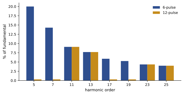
print(f"VLL {VLL} V, firing angle {alpha:>2} deg: Vdc = {1.35 * VLL * np.cos(np.radians(alpha)):6.1f} V")fundamental 78.0 A rms (theory 0.780 Id = 78.0 A) harmonic 3: 0.0 A = 0.0% of fundamental harmonic 5: 15.6 A = 20.0% of fundamental harmonic 7: 11.1 A = 14.3% of fundamental harmonic 11: 7.1 A = 9.1% of fundamental harmonic 13: 6.0 A = 7.7% of fundamental harmonic 17: 4.6 A = 5.9% of fundamental harmonic 19: 4.1 A = 5.3% of fundamental THD (to 199th) 30.8%, displacement-free power factor 0.956 VLL 600 V, firing angle 0 deg: Vdc = 810.0 V VLL 600 V, firing angle 30 deg: Vdc = 701.5 V VLL 600 V, firing angle 60 deg: Vdc = 405.0 V VLL 480 V, firing angle 0 deg: Vdc = 648.0 V VLL 480 V, firing angle 30 deg: Vdc = 561.2 V VLL 480 V, firing angle 60 deg: Vdc = 324.0 V
Real drives with a DC-link capacitor and little inductance draw more peaky current with higher harmonics, typically 70% to over 100% current THD without a reactor, falling to about 35% to 45% with a 3% to 5% line reactor or DC choke. Supply inductance also causes commutation overlap: current takes time to transfer from one diode to the next, reducing the DC voltage by:
Controlled rectifiers
Replacing diodes with thyristors allows the DC voltage to be controlled by delaying each thyristor's firing by an angle \(\alpha\) after the point where a diode would naturally conduct:
For \(0 < \alpha < 90°\) the converter rectifies; for \(90° < \alpha < 180°\) the average voltage is negative and, with current still flowing in the same direction (for example from a DC machine acting as a generator or from the other end of an HVDC link), power flows from the DC side back to the AC system, called inversion. Thyristor converters are used for large DC motor drives, electrolysis, battery chargers, and line-commutated HVDC. Their drawback is that the line current lags the voltage by approximately \(\alpha\), so displacement power factor falls as the output voltage is reduced, and they still produce \(6k \pm 1\) harmonics.
Worked problem
Controlled rectifier operating point
A 600 V thyristor converter supplies a DC motor that needs 500 V. What firing angle is required, and what is the approximate displacement power factor?
Show solution
- \(\cos\alpha = 500/(1.35 \times 600) = 0.617\), so \(\alpha = 51.9°\).
- Displacement power factor \(\approx \cos\alpha = 0.62\) lagging.
Answer: A firing angle of about 52° and a displacement power factor of about 0.62, so the converter draws substantial reactive power at reduced output voltage. Large installations add power factor correction with harmonic filters tuned to absorb the 5th and 7th harmonics.
Multipulse rectifiers
Two six-pulse bridges fed from transformer secondaries phase-shifted by 30° (typically one wye and one delta winding) form a 12-pulse rectifier. The 30° shift causes the 5th, 7th, 17th and 19th harmonics of the two bridges to cancel on the primary side, leaving harmonics of order \(12k \pm 1\) (11th, 13th, 23rd, ...) and reducing current THD to roughly 10% or less. Eighteen-pulse rectifiers (three bridges with 20° shifts) reach about 5% THD and are common in large drives. HVDC converters use 12-pulse configurations with filters for the remaining harmonics.
Active power factor correction and active front ends
The most effective way to eliminate rectifier harmonics is to shape the input current actively. In a single-phase power factor correction (PFC) stage, a boost converter (Lesson 5) after the diode bridge is controlled so that its input current follows a sinusoid in phase with the voltage, while it regulates a DC bus at about 380 V to 400 V. This gives power factors above 0.98 and current THD below 5% to 10% at significant load. Modern server and computer power supplies above modest ratings include active PFC, and high-efficiency designs use bridgeless and totem-pole PFC circuits with SiC or GaN devices to avoid the diode bridge losses.
In three-phase drives and UPS systems, an active front end (AFE) replaces the diode bridge with an IGBT or SiC bridge that operates as a PWM rectifier. It draws nearly sinusoidal current at unity power factor (or a chosen power factor), keeps a regulated DC bus, and can return braking energy to the supply. The cost is more devices, losses and an LCL filter to remove switching-frequency ripple.
Harmonic limits
Harmonic limits at the point of common coupling with the utility are commonly based on IEEE 519 (Standard for Harmonic Control in Electric Power Systems, 2022 edition), which Canadian utilities and engineers widely apply, along with utility interconnection requirements and the CSA C61000-3 series for equipment emissions. IEEE 519 limits voltage distortion at the point of common coupling (for systems at or below 1 kV, 5% for any single harmonic and 8% total) and limits current distortion as a function of the ratio of short-circuit current to load current.
Mitigation options, in rising order of cost and effectiveness, include line reactors and DC chokes, passive tuned filters, multipulse transformers, active harmonic filters (inverters that inject compensating currents), and active front ends. A harmonic study models the system to check compliance and to find resonances with power factor capacitors.
| Front end | Typical current THD | Notes |
|---|---|---|
| Six-pulse, no reactor | 70% to over 100% | Lowest cost; high harmonics |
| Six-pulse with 3% to 5% reactor or DC choke | 30% to 45% | Common baseline for drives |
| 12-pulse | About 10% | Phase-shifting transformer |
| 18-pulse | About 5% | Larger transformer; robust |
| Active front end | Below 5% | Regenerative; unity power factor |
| Six-pulse with active filter | Below 5% | Filter can serve several loads |
Lesson 4 turns to the inductors, transformers and capacitors that these circuits depend on, and Lesson 8 to the filters that keep their switching noise within regulatory limits.
Common mistakes
MistakeCorrecting low power factor of rectifier loads with capacitors alone.
InsteadIdentify whether it is distortion or displacement; capacitors only fix displacement and may resonate.
MistakeSizing a neutral for phase current where single-phase rectifier loads dominate.
InsteadAllow for triplen harmonic currents adding in the neutral.
MistakeUsing Vdc = 1.35 VLL for a capacitor-filtered drive at light load.
InsteadThe DC bus rises toward the peak line voltage at light load.
MistakeIgnoring commutation overlap from supply inductance.
InsteadSubtract 3ωLsId/π from the DC voltage.
MistakeAssuming a 12-pulse rectifier removes all harmonics.
InsteadIt cancels 5th and 7th; 11th, 13th and higher remain.
Summary and key terms
- Single-phase bridges give 0.90 Vrms with resistive loads; capacitor filters charge near the peak.
- Capacitor-input rectifiers draw narrow current pulses with high crest factor and PF around 0.5 to 0.6.
- Power factor = distortion factor × displacement factor; triplen harmonics add in neutrals.
- Six-pulse bridges give 1.35 VLL and harmonics 6k ± 1 with I_h = I_1/h (THD about 31% ideal).
- Thyristor rectifiers give 1.35 VLL cos α; displacement PF falls with α; α > 90° inverts.
- 12-pulse and 18-pulse rectifiers cancel lower harmonics; active PFC and AFEs draw sinusoidal current.
- IEEE 519 sets voltage and current distortion limits at the point of common coupling.
- Rectifier
- A converter from AC to DC.
- Ripple
- The AC variation remaining on a DC output.
- Crest factor
- Peak value divided by rms value.
- Total harmonic distortion
- RMS of harmonics divided by the fundamental.
- Displacement factor
- The cosine of the angle between voltage and fundamental current.
- Triplen harmonics
- Odd multiples of the third harmonic, which add in the neutral.
- Commutation overlap
- The interval when current transfers between rectifier devices.
- Firing angle
- The delay before a thyristor is triggered.
- Multipulse rectifier
- Several phase-shifted bridges that cancel harmonics.
- Active front end
- A PWM rectifier that draws sinusoidal current and can regenerate.
Practice problems
Work each problem on paper first, then reveal the answer to check.
Average output of a single-phase bridge from 120 V rms with a resistive load?
Show answer
0.90 × 120 = 108 V.
Ripple for 5 A DC, 60 Hz, 2,200 µF?
Show answer
5/(2 × 60 × 0.0022) = 18.9 V.
Current THD 80%, displacement factor 1. Power factor?
Show answer
1/√1.64 = 0.78.
Third-harmonic current 20 A per phase. Neutral third-harmonic current?
Show answer
60 A.
DC output of a six-pulse bridge at 600 V?
Show answer
810 V.
Fundamental 100 A in a six-pulse rectifier. 11th harmonic current?
Show answer
100/11 = 9.1 A.
Supply inductance 0.1 mH at 60 Hz, Id = 400 A. Commutation voltage drop?
Show answer
3 × 377 × 0.0001 × 400 / π = 14.4 V.
Firing angle for half the maximum DC voltage?
Show answer
60°.
Which harmonics remain in a 12-pulse rectifier?
Show answer
12k ± 1: 11th, 13th, 23rd, 25th...
What does an active PFC stage do?
Show answer
Shapes input current to a sinusoid in phase with voltage while regulating a DC bus.
Lesson quiz · 5 questions
Score 60% or more to complete this lesson.
Create a free account to save your progress, take quizzes and earn a certificate.