
ELE-203 · Lesson 8 of 12 · 30 min
Unbalanced three-phase systems and symmetrical components
Lesson 7 analysed balanced three-phase systems by solving one phase and shifting the answers by 120°. Real systems are never perfectly balanced: single-phase loads are spread unevenly across phases, a fuse blows on one phase, a conductor breaks, or a fault connects one phase to ground. Unbalance raises neutral currents, distorts voltages, overheats motors and, during faults, produces the currents that protection systems must detect. This lesson studies unbalanced wye and delta loads directly, shows what happens when a neutral is lost, explains how unbalance is measured and why it harms motors, and introduces symmetrical components, the method engineers use to analyse unbalanced conditions and faults.
Unbalanced wye loads with a neutral
If an unbalanced wye load is connected to a four-wire supply with a solid neutral, each phase's load sees its own phase voltage, regardless of the others. Each phase current is simply \(I_a = V_{an}/Z_a\), and so on, and the neutral carries the phasor sum:
Because the currents are 120° apart, the neutral current is much less than their arithmetic sum, and zero when they are balanced. It is not zero for unbalanced loads, and with non-linear loads it can exceed the phase currents, because triplen harmonics (third, ninth and so on) add in the neutral rather than cancelling (Lesson 11).
Worked problem
Neutral current
A 120/208 V wye feeder supplies resistive loads drawing 50 A on phase a, 30 A on phase b and 40 A on phase c. Find the neutral current.
Show solution
- Phasors (resistive loads in phase with their voltages): \(50\angle 0°\), \(30\angle{-120°}\), \(40\angle 120°\).
- Real parts: \(50 - 15 - 20 = 15\); imaginary parts: \(0 - 25.98 + 34.64 = 8.66\).
- \(I_n = 15 + j8.66 = 17.3\angle 30°\) A.
Answer: 17.3 A, compared with 120 A of total phase current. Balancing single-phase loads across phases keeps neutral currents and voltage drops low, which is why panel schedules alternate circuits between phases.
Losing the neutral
If the neutral conductor of a wye-connected unbalanced load opens, the load's star point is no longer held at the source neutral. It floats to a voltage that makes the three phase currents sum to zero, and the load voltages become unequal: phases with small loads (high impedance) get more than their rated voltage, and heavily loaded phases get less. The floating neutral voltage follows from Millman's theorem:
import numpy as np

# 120/208 V wye supply; unbalanced resistive loads per phase (ohms)
Vp = 120.0
Va, Vb, Vc = (Vp * np.exp(1j * np.radians(ang)) for ang in (0, -120, 120))
Za, Zb, Zc = 4.0, 12.0, 24.0

def show(label, Vn):
    vols = [abs(V - Vn) for V in (Va, Vb, Vc)]
    print(f"{label}: neutral shift {abs(Vn):5.1f} V; load voltages a {vols[0]:5.1f}, b {vols[1]:5.1f}, c {vols[2]:5.1f} V")

# With a solid neutral, the load neutral stays at 0 V
show("neutral connected   ", 0)

# With the neutral open, the load star point floats (Millman theorem)
Ya, Yb, Yc = 1 / Za, 1 / Zb, 1 / Zc
Vn = (Va * Ya + Vb * Yb + Vc * Yc) / (Ya + Yb + Yc)
show("neutral disconnected", Vn)neutral connected : neutral shift 0.0 V; load voltages a 120.0, b 120.0, c 120.0 V neutral disconnected: neutral shift 61.1 V; load voltages a 61.1, b 151.4, c 166.5 V
With the neutral open, the lightly loaded phase c sees 167 V, 39% above rating, which can destroy electronics and lamps within seconds, while the heavily loaded phase a sees only 61 V. A lost neutral on a 120/240 V residential service has the same effect between the two halves of a house. This is why neutrals are never fused or switched alone, why their connections must be secure, and why surge and overvoltage complaints in one part of a building often trace to a loose neutral.
Unbalanced delta loads
In a delta load, each impedance is connected directly across a line-to-line voltage, so the phase currents are \(I_{ab} = V_{ab}/Z_{ab}\), etc., independent of each other even when unbalanced. The line currents follow from KCL at each corner:
With unbalanced loads, the line currents are no longer \(\sqrt{3}\) times the phase currents, and must be calculated phasor by phase.
Worked problem
A single-phase load on a three-phase supply
A 20 kW resistive welder is connected between lines a and b of a 480 V three-phase supply, and nothing else is connected. Find the line currents.
Show solution
- \(I_{ab} = 20{,}000/480 = 41.7\) A, in phase with \(V_{ab}\).
- \(I_a = I_{ab} = 41.7\) A; \(I_b = -I_{ab}\), 41.7 A; \(I_c = 0\).
Answer: 41.7 A in lines a and b and none in c. Large single-phase loads on three-phase systems create severe current unbalance; designers spread them across phase pairs, or use phase-balancing equipment for very large loads such as electric arc furnaces and railway traction.
Power in unbalanced systems
The total complex power is the sum of the complex powers of the three phases, \(S = V_{an}I_a^* + V_{bn}I_b^* + V_{cn}I_c^*\), and the convenient balanced formula \(\sqrt{3}V_LI_L\cos\theta\) no longer applies. Measurement follows from Blondel's theorem: in an \(n\)-wire system, \(n - 1\) wattmeters measure total power exactly, whatever the unbalance. A three-wire system therefore needs two wattmeters (the two-wattmeter method of Lesson 7), and a four-wire system three. Revenue meters for three-phase services measure each phase separately for the same reason.
Measuring unbalance and its effects
Voltage unbalance is quantified in two ways:
- The NEMA definition: the maximum deviation of a line voltage from the average of the three, divided by the average, as a percentage.
- The IEC definition: the ratio of negative-sequence to positive-sequence voltage, \(|V_2|/|V_1|\), defined below.
They give similar values for small unbalance. Utilities and standards generally aim to keep voltage unbalance at a service below about 2% to 3%.
Worked problem
NEMA voltage unbalance
Line voltages at a motor are 460 V, 467 V and 450 V. Find the percent voltage unbalance.
Show solution
- Average: \((460 + 467 + 450)/3 = 459\) V.
- Maximum deviation: \(459 - 450 = 9\) V.
- Unbalance: \(9/459 = 1.96\%\).
Answer: About 2%. NEMA MG 1 recommends derating motors when unbalance exceeds 1%: at 2% unbalance the derating factor is about 0.95, at 3% about 0.88, and operation above 5% is not recommended.
Motors are especially sensitive because a small voltage unbalance produces a much larger current unbalance: the negative-sequence voltage drives currents through the motor's low negative-sequence impedance (close to its locked-rotor impedance), creating a reverse-rotating field that brakes the rotor and heats it. As a rule of thumb, current unbalance is six to ten times the voltage unbalance, and temperature rise in the hottest winding increases by roughly twice the square of the percent voltage unbalance.
Symmetrical components
In 1918 Charles Fortescue showed that any set of three unbalanced phasors can be written as the sum of three balanced sets:
- Positive sequence (\(V_1\)): three equal phasors 120° apart in the normal order a, b, c, the component a balanced system has.
- Negative sequence (\(V_2\)): three equal phasors 120° apart in the reverse order a, c, b.
- Zero sequence (\(V_0\)): three equal phasors in phase with each other.
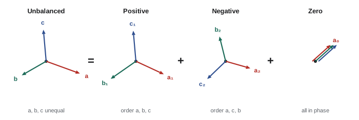
With the operator \(a = 1\angle 120°\), the transformation is
import numpy as np

a = np.exp(2j * np.pi / 3)            # the 120-degree operator
A = np.array([[1, 1, 1], [1, a ** 2, a], [1, a, a ** 2]])

def polar(z):
    return f"{abs(z):7.2f} at {np.degrees(np.angle(z)):7.1f} deg"

# Unbalanced phase currents measured on a feeder (A)
Iabc = np.array([100 * np.exp(1j * np.radians(-20)),
                 80 * np.exp(1j * np.radians(-150)),
                 90 * np.exp(1j * np.radians(95))])
I012 = np.linalg.solve(A, Iabc)
for name, I in zip(("zero", "positive", "negative"), I012):
    print(f"{name:8s} sequence: {polar(I)} A")
print(f"neutral current 3*I0 = {polar(3 * I012[0])} A; direct sum = {polar(Iabc.sum())} A")
print(f"current unbalance I2/I1 = {100 * abs(I012[2]) / abs(I012[1]):.1f}%")

# Check: rebuild the phase currents from the components
print(f"reconstruction error: {np.max(np.abs(A @ I012 - Iabc)):.1e} A")zero sequence: 7.62 at 42.5 deg A positive sequence: 89.77 at -24.6 deg A negative sequence: 7.02 at -16.0 deg A neutral current 3*I0 = 22.86 at 42.5 deg A; direct sum = 22.86 at 42.5 deg A current unbalance I2/I1 = 7.8% reconstruction error: 2.5e-14 A
The components have physical meaning, which is why they are so useful:
- Only the positive sequence does useful work in a motor; the negative sequence brakes and heats it.
- The zero sequence flows only where there is a return path: in the neutral of a grounded wye system, or in the earth. The neutral current is exactly \(3I_0\). Zero-sequence current cannot flow in the lines of a three-wire system, and circulates inside a delta winding without leaving it.
- Balanced, symmetrical equipment such as transmission lines, generators and transformers acts on each sequence independently, with its own positive-, negative- and zero-sequence impedances. An unbalanced problem in a balanced network becomes three uncoupled balanced problems, each solvable per phase.
Faults and sequence networks
The most important application is short-circuit (fault) analysis. The most common fault on overhead lines is a single line-to-ground fault, which is highly unbalanced. Connecting the positive-, negative- and zero-sequence networks of the system in series at the fault point gives the fault current:
where \(V_f\) is the pre-fault phase voltage and \(Z_f\) the fault impedance. A three-phase fault, by contrast, is balanced and involves only the positive-sequence network: \(I_f = V_f/Z_1\).
Worked problem
Line-to-ground fault current
At a 13.8 kV bus (phase voltage 7.97 kV), the sequence impedances are \(Z_1 = Z_2 = j2.0\) Ω and \(Z_0 = j3.5\) Ω. Compare the bolted (Z_f = 0) single line-to-ground and three-phase fault currents.
Show solution
- Three-phase: \(7{,}970/2.0 = 3{,}985\) A.
- Line-to-ground: \(3 \times 7{,}970/(2.0 + 2.0 + 3.5) = 23{,}910/7.5 = 3{,}188\) A.
Answer: About 3.99 kA for a three-phase fault and 3.19 kA for a line-to-ground fault. Where the zero-sequence impedance is low, as near solidly grounded transformers, the line-to-ground fault can exceed the three-phase fault. Utilities control it by grounding through impedance. Fault calculation and protection are developed in ELE-380 and ELE-480.
Common mistakes
MistakeAdding phase current magnitudes to get the neutral current.
InsteadAdd them as phasors; the neutral carries the phasor sum (3I₀).
MistakeAssuming loads keep their voltage when a neutral opens.
InsteadThe star point floats; lightly loaded phases can see dangerous overvoltage.
MistakeUsing √3·V_L·I_L·cos θ for unbalanced loads.
InsteadSum the complex power of each phase, or measure with n − 1 wattmeters.
MistakeTreating 2% voltage unbalance as harmless for motors.
InsteadIt causes much larger current unbalance and heating; derate above 1%.
MistakeExpecting zero-sequence current in a three-wire system's lines.
InsteadZero sequence needs a return path through a neutral or ground.
Summary and key terms
- With a solid neutral, each phase of a wye load is independent; the neutral carries the phasor sum.
- An open neutral lets the star point float, overvolting lightly loaded phases.
- Delta phase currents follow line-to-line voltages; line currents come from KCL at the corners.
- Total power in unbalanced systems is the sum of phase powers; n − 1 wattmeters suffice.
- Voltage unbalance heats motors through negative-sequence currents.
- Symmetrical components split unbalanced sets into positive, negative and zero sequences, the basis of fault analysis.
- Unbalanced load
- A three-phase load with unequal phase impedances.
- Floating neutral
- A load star point not connected to the source neutral.
- Millman's theorem
- A formula for the voltage of a node joined to several sources through admittances.
- Blondel's theorem
- n − 1 wattmeters measure total power in an n-wire system.
- Voltage unbalance
- The deviation of a three-phase voltage set from balance.
- Positive sequence
- A balanced set in the normal phase order.
- Negative sequence
- A balanced set in the reverse phase order.
- Zero sequence
- Three equal, in-phase phasors.
- Sequence impedance
- The impedance a balanced component presents to one sequence.
- Line-to-ground fault
- A short circuit from one phase to ground.
Practice problems
Work each problem on paper first, then reveal the answer to check.
Neutral current for 40 A, 40 A and 40 A resistive phase currents?
Show answer
0 A.
Neutral current for 60∠0°, 0 and 0 A?
Show answer
60 A.
Why are neutrals never fused alone?
Show answer
An open neutral overvolts lightly loaded phases.
Line currents for a 10 kW load between b and c on 400 V?
Show answer
25 A in b and c, 0 in a.
Wattmeters needed for a four-wire system?
Show answer
Three.
NEMA unbalance for 480, 475 and 490 V?
Show answer
Average 481.7; max deviation 8.3; 1.7%.
Which sequence brakes a motor?
Show answer
Negative sequence.
Zero-sequence current if I_a + I_b + I_c = 30∠0° A?
Show answer
10∠0° A.
Bolted three-phase fault current at V_f = 7.2 kV, Z₁ = j1.2 Ω?
Show answer
6 kA.
Line-to-ground fault with Z₁ = Z₂ = j1, Z₀ = j1 Ω, V_f = 7.2 kV?
Show answer
7.2 kA.
Lesson quiz · 5 questions
Score 60% or more to complete this lesson.
Create a free account to save your progress, take quizzes and earn a certificate.