
ELE-203 · Lesson 5 of 12 · 36 min
AC power
In a DC circuit, power is simply voltage times current. In an AC circuit, voltage and current oscillate and are generally out of phase, so the power flowing into a load surges and falls twice each cycle and can even reverse briefly. Part of that flow does useful work, heating, turning motors, running computers, and part merely sloshes back and forth between the source and the magnetic and electric fields of inductors and capacitors. Separating the two is essential for sizing equipment, for understanding electricity bills, and for designing power systems that do not waste capacity carrying current that does no work.
This lesson derives average (real) power, introduces reactive, apparent and complex power and the power triangle, explains power factor and how to correct it, covers maximum power transfer for AC circuits, and briefly treats the non-sinusoidal currents drawn by electronic loads.
Instantaneous and average power
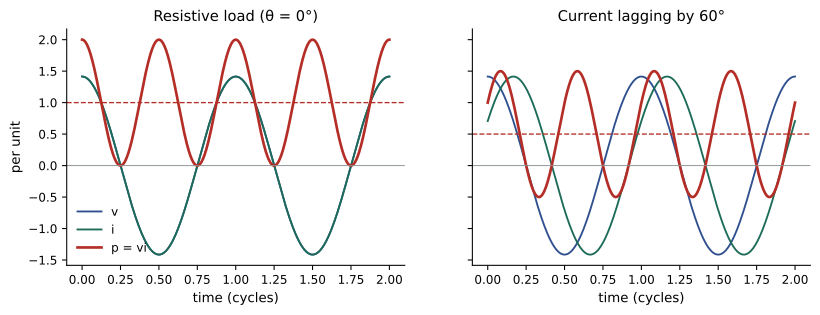
Let a load have voltage \(v = \sqrt2\,V\cos(\omega t + \theta_v)\) and current \(i = \sqrt2\,I\cos(\omega t + \theta_i)\), where \(V\) and \(I\) are RMS values. The instantaneous power, using the identity \(\cos A\cos B = \tfrac12[\cos(A - B) + \cos(A + B)]\), is
The first term is constant; the second oscillates at twice the supply frequency and averages to zero. The average, or real, power is therefore
measured in watts, where \(\theta\) is the angle by which voltage leads current, equal to the angle of the load impedance. For a resistor \(\theta = 0\) and \(P = VI = I^2R = V^2/R\), as in DC, provided RMS values are used. For a pure inductor or capacitor \(\theta = \pm 90°\) and \(P = 0\): energy flows in during one quarter-cycle and returns during the next.
Worked problem
Average power from waveforms
A load has \(v(t) = 170\cos(377t)\) V and \(i(t) = 14.14\cos(377t - 30°)\) A. Find the average power.
Show solution
- RMS values: \(V = 170/\sqrt2 = 120\) V; \(I = 14.14/\sqrt2 = 10.0\) A.
- \(\theta = 0° - (-30°) = 30°\).
- \(P = 120 \times 10 \times \cos 30° = 1039\) W.
Answer: The load absorbs 1039 W on average, even though the product of the RMS values is 1200 VA.
Reactive, apparent and complex power
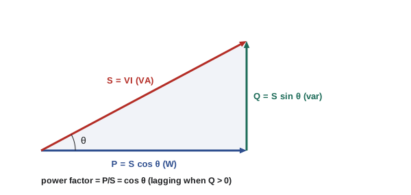
The product \(VI\) is the apparent power \(S\), measured in volt-amperes (VA). It determines the current a source, cable or transformer must carry, and therefore its size, regardless of how much of that current does work. The reactive power
measured in volt-amperes reactive (var), is the amplitude of the energy that oscillates between the source and the load's fields. By convention, inductive loads absorb positive reactive power (\(\theta > 0\), current lagging) and capacitive loads absorb negative reactive power, which is the same as supplying it.
All three are combined in the complex power, computed from phasors as
where \(\mathbf{I}^*\) is the complex conjugate of the current phasor (both phasors with RMS magnitudes). For a load impedance \(\mathbf{Z} = R + jX\), \(\mathbf{S} = I^2\mathbf{Z}\), so \(P = I^2R\) and \(Q = I^2X\): real power is dissipated in resistance and reactive power is associated with reactance.
The three quantities form the power triangle, with \(P\) along the horizontal, \(Q\) vertical and \(S\) as the hypotenuse at angle \(\theta\).
Worked problem
Complex power from phasors
A load has \(\mathbf{V} = 240\angle 0°\) V and \(\mathbf{I} = 20\angle{-30°}\) A. Find S, P, Q and the load impedance.
Show solution
- \(\mathbf{S} = 240\angle 0° \times 20\angle 30° = 4800\angle 30°\) VA.
- \(P = 4800\cos 30° = 4157\) W; \(Q = 4800\sin 30° = 2400\) var (inductive).
- \(\mathbf{Z} = \mathbf{V}/\mathbf{I} = 12\angle 30° = 10.39 + j6.00\) Ω.
- Check: \(I^2R = 400 \times 10.39 = 4157\) W; \(I^2X = 400 \times 6 = 2400\) var.
Answer: S = 4800 VA, P = 4157 W, Q = 2400 var, and Z = 10.39 + j6.00 Ω. Note the conjugate: using \(\mathbf{VI}\) without it would give the wrong sign of Q.
Complex power is conserved: in any circuit, the total complex power delivered by the sources equals the sum of the complex powers absorbed by all the elements. Real powers add, and reactive powers add (with signs). This makes it easy to combine loads without finding every current.
Worked problem
Combining loads
A 240 V, 60 Hz supply feeds three loads in parallel: (1) 5 kW at power factor 0.8 lagging; (2) 3 kVA at power factor 0.6 leading; (3) a 2 kW resistive heater. Find the total complex power, power factor and supply current.
Show solution
- Load 1: \(Q_1 = P\tan\theta = 5 \times \tan(\cos^{-1} 0.8) = 5 \times 0.75 = 3.75\) kvar.
- Load 2: \(P_2 = 3 \times 0.6 = 1.8\) kW; \(Q_2 = -3 \times 0.8 = -2.4\) kvar (leading).
- Load 3: \(P_3 = 2\) kW, \(Q_3 = 0\).
- Total: \(P = 8.8\) kW, \(Q = 1.35\) kvar; \(S = \sqrt{8.8^2 + 1.35^2} = 8.90\) kVA.
- Power factor \(= 8.8/8.90 = 0.988\) lagging; current \(= 8900/240 = 37.1\) A.
Answer: S = 8.8 + j1.35 kVA, a power factor of 0.988 lagging and 37.1 A. The leading load cancels most of the first load's reactive power, so the supply current is only slightly more than the 36.7 A that 8.8 kW would need at unity power factor.
Power factor
The power factor is the ratio of real to apparent power:
It is described as lagging (current lags voltage, inductive load) or leading (capacitive load). Induction motors, transformers and fluorescent ballasts are inductive, with power factors from about 0.7 to 0.9 depending on load; resistive heaters have a power factor of 1; lightly loaded induction motors can fall below 0.5.
A low power factor matters because the current, and hence the losses and voltage drop in every conductor, depend on apparent power. For the same real power, a load at power factor 0.7 draws \(1/0.7 = 1.43\) times the current of a unity-power-factor load and causes \(1.43^2 = 2.04\) times the \(I^2R\) loss in the supply cables. Generators, transformers and cables are rated in VA or amperes, so reactive current uses up capacity that could otherwise carry real power.
Utilities therefore charge large customers for poor power factor. Canadian utilities typically do so through the demand charge or a surcharge: Hydro-Québec, for example, bases the billing demand of many business rates on the greater of the real power demand and 90% of the apparent power demand, which effectively penalizes power factors below 0.9, and other provincial utilities apply power factor surcharges below a similar threshold. Rates differ by utility and change over time, so check the applicable rate schedule.
Power factor correction
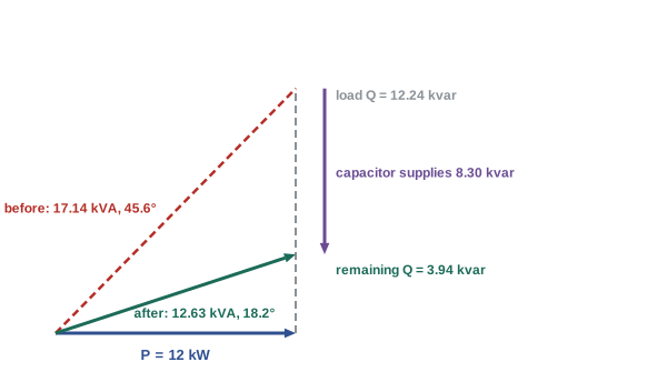
Because inductive loads absorb reactive power and capacitors supply it, a capacitor connected in parallel with an inductive load can supply some or all of the load's reactive power locally. The real power is unchanged, but the reactive power, and hence the current, drawn from the supply falls. To raise the power factor of a load of real power \(P\) from \(\cos\theta_1\) to \(\cos\theta_2\), the capacitor must supply
where \(V\) is the RMS voltage across the capacitor.
Worked problem
Sizing a correction capacitor
A 240 V, 60 Hz single-phase load draws 12 kW at a power factor of 0.70 lagging. Find the capacitance needed to raise the power factor to 0.95 lagging, and the supply current before and after.
Show solution
- \(\theta_1 = \cos^{-1}0.70 = 45.57°\), \(\tan\theta_1 = 1.020\); \(Q_1 = 12 \times 1.020 = 12.24\) kvar.
- \(\theta_2 = \cos^{-1}0.95 = 18.19°\), \(\tan\theta_2 = 0.329\); \(Q_2 = 12 \times 0.329 = 3.94\) kvar.
- \(Q_C = 12.24 - 3.94 = 8.30\) kvar.
- \(C = 8300/(377 \times 240^2) = 382\) µF.
- Current before: \(S_1 = 12/0.70 = 17.14\) kVA, \(I_1 = 71.4\) A. After: \(S_2 = 12/0.95 = 12.63\) kVA, \(I_2 = 52.6\) A.
Answer: About 382 µF (8.3 kvar) cuts the supply current from 71.4 A to 52.6 A, a 26% reduction, and the cable losses by \(1 - (52.6/71.4)^2 = 46\%\). Correcting all the way to unity would need 12.24 kvar for only a small further reduction in current, which is why designers usually aim for about 0.95.
Over-correction is a hazard: a capacitor bank larger than the load's reactive power makes the power factor leading and can raise the voltage, especially when the load switches off and the capacitors remain connected. Large installations use automatic banks that switch capacitor steps in and out as the load changes, and where harmonics are present (below), capacitors are combined with reactors to avoid resonance.
Maximum power transfer
In ELE-202, a resistive load received maximum power from a source with Thévenin resistance \(R_{th}\) when \(R_L = R_{th}\). For an AC source with Thévenin impedance \(\mathbf{Z}_{th} = R_{th} + jX_{th}\), the load receives maximum average power when its impedance is the complex conjugate:
The load reactance cancels the source reactance, leaving a purely resistive circuit, and the load resistance matches the source resistance. If the load is restricted to a pure resistance, the best choice is \(R_L = |\mathbf{Z}_{th}|\), which delivers less power.
Worked problem
Conjugate matching
A source has \(\mathbf{V}_{th} = 20\angle 0°\) V RMS and \(\mathbf{Z}_{th} = 4 + j3\) Ω. Find the load for maximum power and the power delivered. Compare with the best purely resistive load.
Show solution
- Conjugate load: \(\mathbf{Z}_L = 4 - j3\) Ω. Total impedance \(8\) Ω, current \(2.5\) A, \(P = 2.5^2 \times 4 = 25\) W (equal to \(20^2/16\)).
- Resistive load: \(R_L = |4 + j3| = 5\) Ω. Current \(20/|9 + j3| = 20/9.49 = 2.11\) A; \(P = 2.11^2 \times 5 = 22.2\) W.
Answer: The conjugate load 4 − j3 Ω receives 25 W; the best resistive load (5 Ω) receives 22.2 W. Conjugate matching is central in radio-frequency and audio engineering. In power systems it is never used, because matched operation wastes half the power in the source: utilities aim instead for high efficiency, with load impedances far larger than the source impedance.
Non-sinusoidal currents and harmonics
Computers, LED drivers, variable-frequency drives and battery chargers draw current in short pulses rather than as a smooth sinusoid. Such a current can be decomposed (by Fourier analysis, studied in ELE-250) into a fundamental at 60 Hz plus harmonics at integer multiples: 180 Hz (3rd), 300 Hz (5th) and so on. Its RMS value combines them:
where THD is the total harmonic distortion. With a sinusoidal voltage, only the fundamental current delivers average power, so harmonics add current and losses without adding real power. The true power factor then has two parts: the displacement power factor \(\cos\theta_1\) of the fundamental, and the distortion power factor \(I_1/I_{\text{rms}}\).
Worked problem
True power factor of a distorted current
A 120 V electronic load draws a current with a 10 A fundamental lagging by 11.5° (displacement power factor 0.98), a 6 A third harmonic and a 3 A fifth harmonic. Find the RMS current, THD, true power factor and real power.
Show solution
- \(I_{\text{rms}} = \sqrt{10^2 + 6^2 + 3^2} = \sqrt{145} = 12.04\) A.
- THD \(= \sqrt{36 + 9}/10 = 0.671\), or 67%.
- Distortion factor \(= 10/12.04 = 0.830\); true power factor \(= 0.98 \times 0.830 = 0.814\).
- Real power \(= 120 \times 10 \times 0.98 = 1176\) W; apparent power \(= 120 \times 12.04 = 1445\) VA.
Answer: The RMS current is 12.04 A, THD 67% and the true power factor 0.81, even though the displacement power factor is 0.98. A capacitor cannot correct distortion; the remedies are power supplies with active power factor correction, harmonic filters and multi-pulse drives. Third harmonics from many single-phase loads also add up in the neutral of a three-phase system (Lesson 7).
Lesson 11 develops harmonics fully with the Fourier series, including triplen neutral currents and true power factor.
Common mistakes
MistakeComputing power as the product of peak values, or of RMS values without cos θ.
InsteadP = V_rms I_rms cos θ; the product V_rms I_rms is apparent power in VA.
MistakeForgetting the conjugate in S = VI*.
InsteadUse the conjugate of the current phasor, or the sign of Q comes out wrong.
MistakeAdding apparent powers of loads with different power factors.
InsteadAdd real powers and reactive powers separately, then find S from P and Q.
MistakeCorrecting power factor to exactly 1 or beyond.
InsteadAim for about 0.95; over-correction gives leading power factor and overvoltage at light load.
MistakeUsing capacitors to fix a low true power factor caused by harmonics.
InsteadCapacitors fix displacement only; harmonics need filters or better power supplies, and capacitors can resonate with them.
Summary and key terms
- Instantaneous power oscillates at 2ω; average (real) power is P = VI cos θ (RMS values, θ = θv − θi).
- Apparent power S = VI (VA) sets equipment size; reactive power Q = VI sin θ (var) is positive for inductive loads.
- Complex power S = VI* = P + jQ = I²Z; it is conserved, so loads combine by adding P and Q.
- Power factor = P/S = cos θ, lagging for inductive and leading for capacitive loads.
- Low power factor increases current, losses and voltage drop and uses equipment capacity; utilities charge for it.
- Correction capacitor: Q_C = P(tan θ₁ − tan θ₂), C = Q_C/(ωV²); aim for about 0.95.
- Maximum power transfer: Z_L = Z_th*, P_max = |V_th|²/(4R_th); power systems aim for efficiency instead.
- Harmonic currents raise RMS current without adding power; true pf = displacement pf × distortion factor.
- Instantaneous power
- The product p(t) = v(t)i(t) at each instant.
- Real (average) power
- P = VI cos θ, in watts: the power converted to work or heat.
- Reactive power
- Q = VI sin θ, in var: the amplitude of energy oscillating in fields.
- Apparent power
- S = VI, in volt-amperes.
- Complex power
- S = VI* = P + jQ.
- Power triangle
- The right triangle relating P, Q and S.
- Power factor
- The ratio P/S, equal to cos θ for sinusoids.
- Lagging power factor
- Power factor of an inductive load, with current lagging voltage.
- Power factor correction
- Adding capacitors to supply an inductive load's reactive power locally.
- Conjugate matching
- Choosing Z_L = Z_th* to receive maximum power.
- Harmonic
- A sinusoidal component at an integer multiple of the fundamental frequency.
- Total harmonic distortion
- The RMS of the harmonics divided by the fundamental.
- Displacement power factor
- The cosine of the angle between the fundamental voltage and current.
Practice problems
Work each problem on paper first, then reveal the answer to check.
A 120 V circuit carries 15 A at a power factor of 0.85 lagging. Find P, Q and S.
Show answer
S = 1800 VA; P = 1530 W; Q = 1800 × sin(31.8°) = 948 var.
Find the complex power for V = 230∠10° V and I = 5∠−25° A.
Show answer
S = 230∠10° × 5∠25° = 1150∠35° = 942 + j660 VA.
A 20 Ω resistor in series with X_L = 15 Ω is connected to 250 V. Find P, Q and the power factor.
Show answer
|Z| = 25 Ω, I = 10 A; P = 100 × 20 = 2000 W; Q = 1500 var; pf = 0.8 lagging.
A motor delivers 7.5 kW of mechanical power at 90% efficiency and power factor 0.82 lagging. What apparent power does it draw?
Show answer
P_in = 7.5/0.9 = 8.33 kW; S = 8.33/0.82 = 10.2 kVA.
What capacitive kvar raises 100 kW from power factor 0.80 to 0.95?
Show answer
100 × (0.75 − 0.329) = 42.1 kvar.
Find the capacitance that supplies 5 kvar at 240 V, 60 Hz.
Show answer
C = 5000/(377 × 57,600) = 230 µF.
By what percentage do I²R losses fall when the power factor of a fixed real load rises from 0.75 to 0.95?
Show answer
Current scales as 1/pf: losses ∝ 1/pf², ratio (0.75/0.95)² = 0.623, a 38% reduction.
A source has V_th = 50 V RMS and Z_th = 10 − j20 Ω. What load maximizes power, and how much power is that?
Show answer
Z_L = 10 + j20 Ω; P_max = 50²/(4 × 10) = 62.5 W.
A current has a fundamental of 20 A and a THD of 40%. Find its RMS value.
Show answer
Harmonics RMS = 8 A; I_rms = √(400 + 64) = 21.5 A.
Why does a pure capacitor absorb no average power?
Show answer
Its current leads voltage by 90°, so cos θ = 0: it stores energy during one quarter-cycle and returns it during the next.
Lesson quiz · 5 questions
Score 60% or more to complete this lesson.
Create a free account to save your progress, take quizzes and earn a certificate.