
ELE-203 · Lesson 3 of 12 · 35 min
Phasors and impedance
Almost all electric power is generated, transmitted and used as sinusoidal alternating current, and sinusoids are also the building blocks of signals: any periodic waveform can be built from them. When a linear circuit is driven by a sinusoid, every voltage and current in it settles into a sinusoid of the same frequency, differing only in amplitude and phase. Solving for those amplitudes and phases with differential equations is laborious. Phasors replace the calculus with complex-number algebra, so that every technique from ELE-202, including Ohm's law, Kirchhoff's laws, nodal and mesh analysis and Thévenin equivalents, works unchanged for AC circuits.
Sinusoids
A sinusoidal voltage is written
where \(V_m\) is the amplitude (peak value), \(\omega\) the angular frequency in rad/s, and \(\phi\) the phase angle. The frequency in hertz is \(f = \omega/2\pi\) and the period \(T = 1/f\). North American power systems run at 60 Hz, so \(\omega = 2\pi \times 60 = 377\) rad/s and \(T = 16.7\) ms.
This course uses cosine as the reference. A sine is a cosine delayed by 90°: \(\sin\omega t = \cos(\omega t - 90°)\). When comparing two sinusoids of the same frequency, the one whose peaks occur earlier leads the other; \(\cos(\omega t + 30°)\) leads \(\cos\omega t\) by 30°, and \(\cos\omega t\) lags it by 30°.
RMS values
The effective, or root-mean-square (RMS), value of a periodic waveform is the DC value that would deliver the same average power to a resistor:
AC voltages and currents are almost always quoted as RMS values. The 120 V household supply has a peak of \(120\sqrt{2} = 170\) V, and a 600 V industrial system has line-to-line peaks of 849 V. Meters labelled "true RMS" compute the RMS of any waveform; cheaper meters assume a sinusoid and read incorrectly on distorted waveforms, such as the current drawn by electronic power supplies.
Complex numbers
Phasors use complex numbers, written in rectangular form \(z = x + jy\) (engineers use \(j\) for \(\sqrt{-1}\), because \(i\) denotes current) or polar form \(z = r\angle\theta\), where \(r = \sqrt{x^2 + y^2}\) and \(\theta = \tan^{-1}(y/x)\) (adjusted to the correct quadrant). The two are related by \(x = r\cos\theta\), \(y = r\sin\theta\), and Euler's formula connects them to the exponential:
Addition and subtraction are easiest in rectangular form; multiplication and division in polar form, where magnitudes multiply or divide and angles add or subtract. The complex conjugate \(z^* = x - jy = r\angle{-\theta}\). Most engineering calculators handle both forms directly, and it is worth learning to use that feature.
Worked problem
Complex arithmetic
With \(A = 3 + j4\) and \(B = 10\angle{-30°}\), find \(A + B\), \(AB\) and \(A/B\).
Show solution
- Convert: \(A = 5\angle 53.13°\); \(B = 8.660 - j5.000\).
- \(A + B = 11.660 - j1.000 = 11.70\angle{-4.90°}\).
- \(AB = (5 \times 10)\angle(53.13° - 30°) = 50\angle 23.13°\).
- \(A/B = 0.5\angle 83.13°\).
Answer: \(A + B = 11.70\angle{-4.90°}\), \(AB = 50\angle 23.13°\), \(A/B = 0.5\angle 83.13°\).
Phasors
By Euler's formula, \(V_m\cos(\omega t + \phi) = \text{Re}\{V_m e^{j\phi} e^{j\omega t}\}\). In a circuit where every quantity oscillates at the same \(\omega\), the factor \(e^{j\omega t}\) is common to everything and can be dropped. What remains, the complex number carrying amplitude and phase, is the phasor:
Geometrically, the phasor is an arrow of length \(V_m\) at angle \(\phi\); the real signal is the projection onto the real axis of that arrow rotating counterclockwise at \(\omega\). In power engineering, phasors are usually written with RMS magnitude (120∠0° V rather than 170∠0° V); either convention works if it is used consistently, and this course states which is used. Here, unless stated otherwise, phasor magnitudes are RMS.
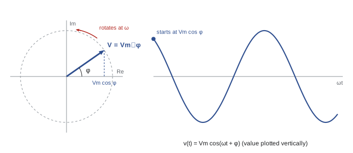
The key property of phasors is that differentiation becomes multiplication by \(j\omega\), and integration division by \(j\omega\), because \(\frac{d}{dt}e^{j\omega t} = j\omega e^{j\omega t}\). That turns the differential equations of capacitors and inductors into algebraic equations.
Impedance
Applying the phasor rule to each element's equation gives a ratio of voltage phasor to current phasor called impedance, \(\mathbf{Z} = \mathbf{V}/\mathbf{I}\), measured in ohms:
| Element | Time domain | Impedance | Phase of V relative to I |
|---|---|---|---|
| Resistor | v = Ri | Z = R | In phase |
| Inductor | v = L di/dt | Z = jωL | V leads I by 90° |
| Capacitor | i = C dv/dt | Z = 1/(jωC) = −j/(ωC) | V lags I by 90° |
The magnitudes \(X_L = \omega L\) and \(X_C = 1/(\omega C)\) are the inductive and capacitive reactances. An inductor's impedance grows with frequency (it is a short circuit at DC and an open circuit at very high frequency); a capacitor's falls with frequency (open at DC, short at very high frequency). A useful memory aid is "ELI the ICE man": in an inductor (L), voltage (E) leads current (I); in a capacitor (C), current leads voltage.
A general impedance is \(\mathbf{Z} = R + jX\): its real part is resistance and its imaginary part reactance, positive for inductive and negative for capacitive circuits. The reciprocal, admittance \(\mathbf{Y} = 1/\mathbf{Z} = G + jB\), measured in siemens, is convenient for parallel circuits.
Impedances combine exactly like resistances: in series they add, in parallel their admittances add, and \(\mathbf{Z}_1 \parallel \mathbf{Z}_2 = \mathbf{Z}_1\mathbf{Z}_2/(\mathbf{Z}_1 + \mathbf{Z}_2)\). Voltage and current dividers, delta-wye transformations, nodal and mesh analysis, superposition, and Thévenin and Norton equivalents all carry over with complex numbers in place of real ones.
Worked problem
Series RL circuit
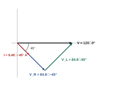
A 120 V, 60 Hz source supplies a coil modelled as 10 Ω in series with 26.5 mH. Find the impedance, the current and the voltage across each element, and draw the phasor diagram.
Show solution
- \(X_L = 377 \times 0.0265 = 10.0\) Ω, so \(\mathbf{Z} = 10 + j10 = 14.14\angle 45°\) Ω.
- Taking the source as reference, \(\mathbf{I} = 120\angle 0° / 14.14\angle 45° = 8.49\angle{-45°}\) A.
- \(\mathbf{V}_R = 10 \times 8.49\angle{-45°} = 84.9\angle{-45°}\) V.
- \(\mathbf{V}_L = j10 \times 8.49\angle{-45°} = 84.9\angle 45°\) V.
- Check: \(\mathbf{V}_R + \mathbf{V}_L = (60.0 - j60.0) + (60.0 + j60.0) = 120\angle 0°\) V.
Answer: Z = 14.14∠45° Ω; the current is 8.49 A lagging the voltage by 45°; each element has 84.9 V across it. The element voltages add to 120 V as phasors, not as numbers (84.9 + 84.9 = 169.8 V would be wrong), because they are 90° apart.
Worked problem
Series RC divider
A 10 V RMS, 1 kHz sinusoid drives a 1 kΩ resistor in series with a 159 nF capacitor. Find the voltage across the capacitor.
Show solution
- \(\omega = 2\pi \times 1000 = 6283\) rad/s; \(X_C = 1/(6283 \times 159 \times 10^{-9}) = 1001\) Ω ≈ 1 kΩ.
- \(\mathbf{Z} = 1000 - j1000 = 1414\angle{-45°}\) Ω.
- Voltage divider: \(\mathbf{V}_C = 10\angle 0° \times \dfrac{-j1000}{1000 - j1000} = 10 \times \dfrac{1000\angle{-90°}}{1414\angle{-45°}} = 7.07\angle{-45°}\) V.
Answer: The capacitor voltage is 7.07 V, lagging the input by 45°. At this frequency \(X_C = R\), which is the cutoff frequency of the RC low-pass filter studied in Lesson 9: the output is 1/√2 of the input.
Parallel circuits and admittance
Worked problem
Parallel RLC load
A 240 V, 60 Hz supply feeds three parallel branches: 20 Ω, an inductor with \(X_L = 15\) Ω and a capacitor with \(X_C = 30\) Ω. Find the current in each branch and the total current.
Show solution
- \(\mathbf{I}_R = 240/20 = 12\angle 0°\) A.
- \(\mathbf{I}_L = 240/(j15) = 16\angle{-90°} = -j16\) A.
- \(\mathbf{I}_C = 240/(-j30) = 8\angle 90° = j8\) A.
- Total: \(12 - j16 + j8 = 12 - j8 = 14.42\angle{-33.7°}\) A.
- Equivalently, \(\mathbf{Y} = 0.05 - j0.0667 + j0.0333 = 0.05 - j0.0333\) S, and \(\mathbf{I} = 240\,\mathbf{Y}\).
Answer: Branch currents 12 A, 16 A and 8 A, but a total of only 14.4 A lagging by 33.7°, because the inductor and capacitor currents are 180° apart and partly cancel. This cancellation is the basis of power factor correction (Lesson 5).
AC circuit analysis
Nodal and mesh analysis proceed exactly as in ELE-202, producing simultaneous linear equations with complex coefficients. The steps are: convert every source to a phasor and every element to an impedance at the source frequency; solve with the usual method; convert the phasor answers back to time functions if needed. If sources of different frequencies are present, they must be analysed separately (each with its own impedances) and the time-domain results added by superposition; phasors of different frequencies cannot be added.
Worked problem
Nodal analysis with phasors
A node \(\mathbf{V}\) connects to a source \(\mathbf{V}_s = 100\angle 0°\) V through \(j10\) Ω, to ground through 20 Ω, and to ground through \(-j20\) Ω. Find \(\mathbf{V}\).
Show solution
- KCL at the node: \(\dfrac{\mathbf{V} - 100}{j10} + \dfrac{\mathbf{V}}{20} + \dfrac{\mathbf{V}}{-j20} = 0\).
- Using admittances: \(-j0.1(\mathbf{V} - 100) + 0.05\mathbf{V} + j0.05\mathbf{V} = 0\).
- \(\mathbf{V}(0.05 - j0.05) = -j10\), so \(\mathbf{V} = \dfrac{10\angle{-90°}}{0.0707\angle{-45°}} = 141.4\angle{-45°}\) V.
Answer: \(\mathbf{V} = 141.4\angle{-45°}\) V, larger than the 100 V source. In AC circuits an inductor and capacitor can partly resonate and produce voltages greater than the source, which never happens in resistive circuits.
Worked problem
AC Thévenin equivalent
In the previous circuit, treat the 20 Ω resistor as a load and find the Thévenin equivalent of the rest of the circuit as seen by it. Use it to check the earlier answer.
Show solution
- Remove the 20 Ω load. Open-circuit voltage by divider: \(\mathbf{V}_{th} = 100 \times \dfrac{-j20}{j10 - j20} = 100 \times \dfrac{-j20}{-j10} = 200\angle 0°\) V.
- With the source shorted: \(\mathbf{Z}_{th} = j10 \parallel (-j20) = \dfrac{(j10)(-j20)}{j10 - j20} = \dfrac{200}{-j10} = j20\) Ω.
- Check: load current \(200/(20 + j20) = 7.07\angle{-45°}\) A, so the load voltage is \(141.4\angle{-45°}\) V, as before.
Answer: \(\mathbf{V}_{th} = 200\angle 0°\) V and \(\mathbf{Z}_{th} = j20\) Ω. AC Thévenin equivalents are used in Lesson 5 for maximum power transfer and throughout power systems for fault and voltage calculations.
Lesson 4 applies phasors systematically, with nodal and mesh analysis, Thévenin equivalents, superposition of different frequencies and op-amp circuits.
Common mistakes
MistakeAdding AC voltage magnitudes around a loop.
InsteadAdd phasors (complex numbers); magnitudes add only when the phasors are in phase.
MistakeMixing peak and RMS values in one calculation.
InsteadChoose one convention (RMS in power work) and convert every quantity to it.
MistakeUsing the wrong sign for capacitive impedance.
InsteadZ_C = 1/(jωC) = −j/(ωC): capacitive reactance is negative.
MistakeForgetting to convert frequency in hertz to angular frequency.
InsteadReactances use ω = 2πf (377 rad/s at 60 Hz).
MistakeAdding phasors of sources at different frequencies.
InsteadAnalyse each frequency separately and add the time-domain results.
MistakeTaking arctan of y/x without checking the quadrant.
InsteadLocate the point in the complex plane; −3 − j4 is at −126.9°, not 53.1°.
Summary and key terms
- A sinusoid \(V_m\cos(\omega t + \phi)\) has amplitude, angular frequency (ω = 2πf, 377 rad/s at 60 Hz) and phase.
- RMS value = \(V_m/\sqrt{2}\) for a sinusoid; AC quantities are normally quoted as RMS.
- Complex numbers: add in rectangular form, multiply and divide in polar form; \(e^{j\theta} = \cos\theta + j\sin\theta\).
- A phasor \(V_m\angle\phi\) represents a sinusoid at a known frequency; differentiation becomes multiplication by jω.
- Impedances: R, jωL and 1/(jωC); inductors lead, capacitors lag (ELI the ICE man).
- Z = R + jX; Y = 1/Z = G + jB. Impedances combine like resistances.
- All DC analysis methods (dividers, nodal, mesh, superposition, Thévenin) work with phasors and impedances.
- Analyse sources of different frequencies separately.
- Amplitude
- The peak value of a sinusoid.
- Angular frequency
- ω = 2πf, in radians per second.
- Phase angle
- The angle φ that sets where a sinusoid's peak occurs relative to t = 0.
- RMS value
- The DC value that delivers the same average power to a resistor; Vm/√2 for a sinusoid.
- Phasor
- A complex number representing the amplitude and phase of a sinusoid.
- Impedance
- The ratio of voltage phasor to current phasor, Z = R + jX.
- Reactance
- The imaginary part of impedance: ωL for an inductor, −1/(ωC) for a capacitor.
- Admittance
- The reciprocal of impedance, Y = G + jB.
- Leading
- Reaching its peak earlier in time (a positive phase difference).
- Lagging
- Reaching its peak later in time (a negative phase difference).
- Phasor diagram
- A drawing of phasors as arrows showing magnitudes and phase relationships.
Practice problems
Work each problem on paper first, then reveal the answer to check.
Express \(v(t) = 311\sin(314t + 20°)\) V as an RMS phasor, and give its frequency.
Show answer
sin(θ) = cos(θ − 90°): 311 cos(314t − 70°); RMS 220 V: 220∠−70° V; f = 314/2π = 50 Hz.
Convert −3 − j4 to polar form and 20∠150° to rectangular form.
Show answer
5∠−126.87°; −17.32 + j10.
Find the reactance of 50 mH and of 47 µF at 60 Hz.
Show answer
X_L = 377 × 0.05 = 18.85 Ω; X_C = 1/(377 × 47 × 10⁻⁶) = 56.4 Ω.
At what frequency does a 10 mH inductor have the same reactance as a 10 µF capacitor?
Show answer
ω = 1/√(LC) = 1/√(10⁻⁷) = 3162 rad/s; f = 503 Hz.
Find the impedance of 30 Ω in series with 0.1 H and 100 µF at 60 Hz.
Show answer
X_L = 37.7, X_C = 26.5: Z = 30 + j11.2 = 32.0∠20.5° Ω.
What current flows if 120 V at 60 Hz is applied to the impedance of the previous question?
Show answer
120/32.0∠20.5° = 3.75∠−20.5° A.
Find the parallel combination of 10 Ω and −j10 Ω.
Show answer
(10)(−j10)/(10 − j10) = −j100/(14.14∠−45°) = 7.07∠−45° = 5 − j5 Ω.
A coil draws 2 A from 120 V, 60 Hz with the current lagging by 60°. Find its resistance and inductance.
Show answer
Z = 60∠60° = 30 + j51.96 Ω: R = 30 Ω, L = 51.96/377 = 0.138 H.
Two series elements have voltages 30∠0° V and 40∠90° V. What is the total voltage?
Show answer
30 + j40 = 50∠53.1° V.
A circuit is driven by 10 V DC plus 5 V at 1 kHz. How is it analysed?
Show answer
By superposition: a DC analysis (capacitors open, inductors shorted) and a phasor analysis at 1 kHz, with the time-domain results added.
Lesson quiz · 5 questions
Score 60% or more to complete this lesson.
Create a free account to save your progress, take quizzes and earn a certificate.