
DCE-330 · Lesson 4 of 12 · 29 min
Cooling units and terminal equipment
Lesson 3 described how air must be delivered to IT inlets and returned without mixing. The equipment that actually removes heat from the air, the terminal units, comes in many forms: perimeter computer room air handlers, fan walls, in-row coolers, rear-door heat exchangers and overhead units. Each has a different capacity, footprint, efficiency and failure behaviour, and the choice shapes the hall layout. This lesson explains how cooling coils work and why their capacity depends on temperatures, compares the main types of terminal equipment, and shows how to select and size them, including redundancy and the control of their fans.
How a cooling coil works
Most terminal units cool air with a finned-tube coil carrying chilled water or refrigerant. Air passes over the fins and gives up heat to the fluid inside the tubes. The heat transferred depends on the temperature difference between air and fluid, the coil's conductance (its area and heat-transfer coefficients, together called UA), and the flow rates of air and water. The effectiveness-NTU method expresses this neatly: the coil transfers a fraction \(\varepsilon\) (its effectiveness) of the maximum possible heat,
where \(C_{min}\) is the smaller of the air and water heat-capacity rates. The consequence for data centres is direct: a coil's capacity rises roughly in proportion to the difference between the entering air temperature and the entering water temperature. Hotter return air, from good containment, and the same water temperature give more capacity from the same coil.
import math

# A chilled-water CRAH coil modelled with the effectiveness-NTU method (counterflow)
UA = 22.0            # kW/K, coil conductance
air_flow = 12.0      # m3/s
C_air = 1.2 * air_flow * 1.006         # kW/K
water_flow = 4.0     # L/s
C_w = water_flow * 4.18                # kW/K

def capacity(t_air_in, t_w_in):
    cmin, cmax = min(C_air, C_w), max(C_air, C_w)
    cr = cmin / cmax
    ntu = UA / cmin
    eff = (1 - math.exp(-ntu * (1 - cr))) / (1 - cr * math.exp(-ntu * (1 - cr)))
    q = eff * cmin * (t_air_in - t_w_in)
    return q, t_air_in - q / C_air, t_w_in + q / C_w

for t_ret in (28.0, 32.0, 36.0, 40.0):
    q, t_sup, t_wout = capacity(t_ret, 18.0)
    print(f"return air {t_ret:4.1f} C: capacity {q:5.0f} kW, supply air {t_sup:4.1f} C, water out {t_wout:4.1f} C")

# Units needed for a 1.2 MW hall at 36 C return, N+1
q36 = capacity(36.0, 18.0)[0]
n = math.ceil(1200 / q36)
print(f"units for 1,200 kW at 36 C return: N = {n}, installed N+1 = {n + 1}")return air 28.0 C: capacity 91 kW, supply air 21.7 C, water out 23.4 C return air 32.0 C: capacity 127 kW, supply air 23.2 C, water out 25.6 C return air 36.0 C: capacity 164 kW, supply air 24.7 C, water out 27.8 C return air 40.0 C: capacity 200 kW, supply air 26.2 C, water out 30.0 C units for 1,200 kW at 36 C return: N = 8, installed N+1 = 9
Manufacturers' catalogues rate units at standard conditions, often older ones with 24 °C return air and 7 °C water. A unit rated at 150 kW at those conditions may deliver far less at 18 °C water unless the return air is hot. Selection must use the actual design temperatures, from the manufacturer's selection software or a coil model like the one above.
Worked problem
Containment and unit count
A 1.2 MW hall uses the coil in the code. Without containment, mixing limits return air to 28 °C; with hot-aisle containment it reaches 36 °C. How many units are needed in each case for N+1 redundancy?
Show solution
- At 28 °C: 91 kW each; \(1{,}200/91 = 13.2\), so N = 14 and 15 installed.
- At 36 °C: 164 kW each; \(1{,}200/164 = 7.3\), so N = 8 and 9 installed.
Answer: 15 units without containment, 9 with it: six fewer units, with their floor space, piping and fan power. Containment pays for itself largely through this effect.
Types of terminal equipment
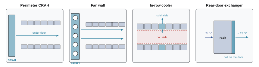
| Type | Typical capacity | Strengths | Limitations |
|---|---|---|---|
| Perimeter CRAH/CRAC | 50–250 kW per unit | Mature, serviceable outside the IT area | Long air paths; depends on raised floor or ducting; mixing without containment |
| Fan wall (air handler gallery) | Hundreds of kW to MW per wall | Large, efficient fans; no water in the hall; scalable | Needs a gallery and large openings; less suited to very high density |
| In-row cooler | 20–70 kW | Short air path, close-coupled to load; good for medium density | Takes rack positions; water or refrigerant in the row |
| Rear-door heat exchanger | 20–80 kW per rack | Neutralizes heat at the rack; uses server fans (passive) or adds fans (active) | Water at every rack; door weight and service access |
| Overhead cooler | 10–40 kW | No floor space used | Refrigerant or water above IT; limited capacity |
A CRAC (computer room air conditioner) has its own compressor and refrigerant circuit and rejects heat to an outdoor condenser; a CRAH (computer room air handler) has only fans and a chilled-water coil, served by a central plant (Lesson 5). Large modern facilities mostly use CRAHs, fan walls or air handlers with economizers; CRACs remain common in smaller rooms.
Fan walls
Hyperscale halls often place large arrays of fans and coils in a gallery along one or two sides of the hall, pushing cold air across the room at low velocity into the cold aisles, with hot aisles contained and ducted back to the gallery. Many smaller fans in an array provide redundancy (losing one fan of twenty barely changes capacity), run at reduced speed most of the time, and can be serviced without entering the IT space. Their air paths are short and unobstructed, which keeps fan power low.
Close-coupled cooling
In-row coolers and rear-door heat exchangers place the coil next to, or on, the heat source. Short air paths mean little mixing and low fan energy, and capacity can be added where density rises. Their cost is water (or refrigerant) piped to every row or rack, with leak detection and drip management, and space in or on the rack line.
A passive rear-door heat exchanger has no fans: the servers' own fans push exhaust air through the coil. It is called room-neutral when it cools the exhaust back to the room temperature, so the rack adds no heat to the room.
# Rear-door heat exchanger (RDHx) on high-density racks
cp_air = 1.2 * 1.006          # kJ per m3 per K
for rack_kw, dT_server in ((20, 12.0), (40, 14.0), (60, 15.0)):
    airflow = rack_kw / (cp_air * dT_server)          # m3/s through the servers
    t_in = 24.0
    t_exh = t_in + dT_server
    for eff in (0.6, 0.8):
        # door cools exhaust toward the 22 C water supply with effectiveness eff
        t_out = t_exh - eff * (t_exh - 22.0)
        removed = airflow * cp_air * (t_exh - t_out)
        left = rack_kw - removed
        print(f"{rack_kw:3d} kW rack, {airflow:4.2f} m3/s, exhaust {t_exh:4.1f} C, door eff {eff:.2f}: "
f"leaves {t_out:4.1f} C, removes {removed:5.1f} kW, {left:5.1f} kW to the room")20 kW rack, 1.38 m3/s, exhaust 36.0 C, door eff 0.60: leaves 27.6 C, removes 14.0 kW, 6.0 kW to the room 20 kW rack, 1.38 m3/s, exhaust 36.0 C, door eff 0.80: leaves 24.8 C, removes 18.7 kW, 1.3 kW to the room 40 kW rack, 2.37 m3/s, exhaust 38.0 C, door eff 0.60: leaves 28.4 C, removes 27.4 kW, 12.6 kW to the room 40 kW rack, 2.37 m3/s, exhaust 38.0 C, door eff 0.80: leaves 25.2 C, removes 36.6 kW, 3.4 kW to the room 60 kW rack, 3.31 m3/s, exhaust 39.0 C, door eff 0.60: leaves 28.8 C, removes 40.8 kW, 19.2 kW to the room 60 kW rack, 3.31 m3/s, exhaust 39.0 C, door eff 0.80: leaves 25.4 C, removes 54.4 kW, 5.6 kW to the room
The heat left to the room must still be removed by other equipment, and if water to the doors stops, the full rack load is dumped into the room at once. Designs therefore keep some room-level cooling capacity and alarm on door water flow and exhaust temperature.
Fans and their control
Fans are the largest energy use in many terminal units. From the fan laws (Lesson 3), airflow is proportional to speed and power to the cube of speed, so running more fans more slowly saves energy: two fans at 50% speed deliver the same airflow as one at 100% for about a quarter of the power. Modern units use electronically commutated (EC) motors or variable-frequency drives, and redundancy is often run as "all units on at reduced speed" rather than "one unit off as standby". The standby unit then contributes capacity and saves energy, and if any unit fails, the others speed up.
Worked problem
Running the redundant unit
A hall needs 40 m³/s of air. Each of 5 units can deliver 10 m³/s at 100% speed, drawing 8 kW. Compare running 4 units at 100% with the fifth off, against all 5 at 80%.
Show solution
- 4 at 100%: \(4 \times 8 = 32\) kW.
- 5 at 80%: each draws \(8 \times 0.8^3 = 4.1\) kW; total 20.5 kW.
- Saving: \(32 - 20.5 = 11.5\) kW, or 36%.
Answer: All five at 80% saves about 11.5 kW, roughly 100 MWh per year, while still providing N+1 redundancy, because if one fails the other four ramp to 100%.
What controls the fans?
Fans in contained halls are commonly controlled to keep a small positive pressure difference between the cold aisle and the hot aisle (a few pascals), so that IT fans always find enough cold air, while the coil's water valve controls the supply air temperature. Older systems controlled unit return-air temperature, which led to unstable behaviour and over-cooling. Lesson 8 covers control sequences in detail.
Refrigerant-based units
Direct-expansion (DX) units use a refrigerant circuit in each unit, with outdoor condensers or a pumped refrigerant economizer. They avoid chilled-water piping in the building and suit small and medium rooms and sites without water. Pumped refrigerant economizers circulate refrigerant with a small pump instead of the compressor when it is cold outdoors, a form of free cooling. Their limitations are lower efficiency than large chilled-water plants in warm weather, many separate compressors to maintain, and refrigerant charge spread across the building, which matters as refrigerant regulations tighten (Lesson 5).
Selecting and sizing
A practical selection process:
- Establish the design load per zone and its growth, and the density range per rack (Lesson 1).
- Choose design temperatures: supply air within the ASHRAE recommended range (often 22 °C to 27 °C), expected return air with containment, and water temperatures from the plant design.
- Choose the terminal type by density: perimeter or fan wall for low to medium density with containment, close-coupled for medium to high, and liquid cooling beyond what air can handle (Lessons 9 and 10).
- Size units at actual design conditions, including derating for altitude (thinner air carries less heat) and glycol if used.
- Add redundancy (N+1, N+2 or 2N, Lesson 11), placing redundant units so that the loss of any one does not leave a zone uncovered.
- Check fan power, noise, service access, and the effect of a unit failure on the airflow pattern, using CFD where the layout is complex (Lesson 3).
Worked problem
Altitude derating
A unit delivers 150 kW at sea level with a fixed volumetric airflow. At Calgary (about 1,050 m), air density is about 12% lower. What capacity should be assumed if the temperature difference is unchanged?
Show solution
- Heat carried is proportional to mass flow: \(Q = \rho\dot{V}c_p\Delta t\).
- With 12% lower density: \(150 \times 0.88 = 132\) kW.
Answer: About 132 kW, unless the fans can run faster to restore the mass flow (at about 1.47 times the fan power). High-altitude sites need more airflow or more units for the same load.
Common mistakes
MistakeSelecting units from catalogue ratings at old standard conditions.
InsteadSelect at the actual return-air and water temperatures of the design.
MistakeKeeping the redundant unit switched off.
InsteadRun all units at reduced speed; fan power falls with the cube of speed.
MistakeAssuming rear doors remove all rack heat.
InsteadCheck door effectiveness and water temperature; keep room cooling for residual heat and door failures.
MistakeControlling units on their own return-air temperature.
InsteadControl supply-air temperature and aisle pressure difference.
MistakeIgnoring altitude.
InsteadDerate air-side capacity for lower air density at high sites.
Summary and key terms
- Coil capacity depends on UA, flows and the air-to-water temperature difference.
- Hot return air from containment greatly increases capacity per unit.
- Terminal options: perimeter CRAH/CRAC, fan walls, in-row coolers, rear doors and overhead units.
- Rear-door exchangers can be room-neutral but need backup room cooling.
- Run redundant fans at reduced speed; control supply temperature and aisle pressure.
- Size at real conditions, with altitude, glycol and redundancy included.
- CRAC
- Computer room air conditioner with its own refrigerant circuit.
- CRAH
- Computer room air handler with a chilled-water coil and fans.
- Effectiveness
- The fraction of the maximum possible heat a heat exchanger transfers.
- UA
- A heat exchanger's overall conductance.
- Fan wall
- An array of fans and coils in a gallery supplying a hall.
- In-row cooler
- A cooling unit placed between racks in a row.
- Rear-door heat exchanger
- A coil mounted on the back of a rack.
- Room-neutral
- Returning air to the room at the room temperature.
- EC motor
- An electronically commutated, efficient variable-speed motor.
- Pumped refrigerant economizer
- A DX system mode that pumps refrigerant without the compressor in cold weather.
Practice problems
Work each problem on paper first, then reveal the answer to check.
What happens to coil capacity if return air rises with the same water temperature?
Show answer
It increases roughly in proportion to the air-water temperature difference.
Coil with ε = 0.7, C_min = 14 kW/K, air in 35 °C, water in 18 °C: Q?
Show answer
0.7 × 14 × 17 = 167 kW.
Difference between a CRAC and a CRAH?
Show answer
A CRAC has its own compressor; a CRAH uses chilled water.
Why do fan walls tolerate fan failures well?
Show answer
Many fans share the load; losing one changes capacity little.
What does room-neutral mean for a rear door?
Show answer
It returns exhaust air at room temperature, adding no heat to the room.
Power of 6 fans at 70% versus 4 at 100% (8 kW each)?
Show answer
6 × 8 × 0.343 = 16.5 kW versus 32 kW.
What variable is usually controlled by fan speed in contained halls?
Show answer
The pressure difference between cold and hot aisles.
Capacity at 20% lower air density, fixed airflow and ΔT, of a 100 kW unit?
Show answer
80 kW.
When are DX units a good choice?
Show answer
Small or medium rooms, sites without water.
Units for 900 kW at 120 kW each, N+1?
Show answer
8 + 1 = 9.
Lesson quiz · 5 questions
Score 60% or more to complete this lesson.
Create a free account to save your progress, take quizzes and earn a certificate.