
DCE-330 · Lesson 10 of 12 · 27 min
Cooling AI and high-density halls
Lesson 9 described direct-to-chip and immersion liquid cooling at the level of the rack. This lesson scales up to a whole hall built for AI training and inference, where racks draw 100 kW or more, most of the heat leaves in liquid, the rest still needs air, and the facility must be designed for loads that change in seconds. The decisions involve the split between liquid and air, the facility and technology cooling loops and the coolant distribution units between them, temperatures chosen for efficient heat rejection, transient behaviour, the construction and commissioning of liquid systems, and how to plan halls that can absorb several generations of increasingly dense hardware.
The shape of the load
An AI training rack today can draw 40 kW to more than 130 kW; rack-scale systems with dozens of accelerators interconnected in one rack are at the high end, and roadmaps point higher. Three features distinguish these loads from conventional IT:
- Density: the heat of an entire conventional row in one rack.
- Split heat paths: cold plates remove the processor and memory heat, typically 70% to 90% of the rack, while power supplies, network cards, storage and other components still reject heat to air.
- Synchronous, fluctuating power: thousands of accelerators in a training job compute and then exchange data in lockstep, so the power of a whole hall can swing by tens of percent within seconds. This affects both electrical systems and cooling.
Two loops and the CDU
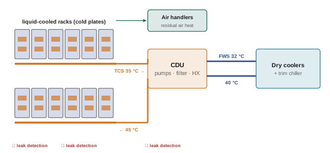
Liquid cooling in a hall uses two loops separated by coolant distribution units (CDUs):
- The technology cooling system (TCS), or secondary loop, circulates a treated coolant (water with inhibitors, or a glycol mixture) through the racks' cold plates. It is a clean, closed, finely filtered loop with tight control of pressure, flow, temperature and chemistry.
- The facility water system (FWS), or primary loop, carries heat from the CDUs to heat rejection: dry coolers, cooling towers, chillers, or a heat-reuse system.
The CDU contains a liquid-to-liquid heat exchanger, pumps for the TCS, filtration, an expansion tank, and controls. Liquid-to-air CDUs (sometimes called sidecars) instead reject the heat to the room's air, useful where no facility water exists, at the cost of adding the heat back to the air-cooling system.
import math

# A 64-rack AI hall with liquid-cooled racks: split the heat, size CDUs and flows
racks, rack_kw, liquid_share = 64, 130.0, 0.85
cdu_kw = 1500.0                   # liquid-to-liquid CDU rating at design temperatures
tcs_dT, fws_dT = 10.0, 8.0        # K, secondary (TCS) and facility (FWS) loop temperature rises
cp = 4.18                         # kJ/kg K (water-based coolant, approximate)

it = racks * rack_kw
liquid = it * liquid_share
air = it - liquid
n = math.ceil(liquid / cdu_kw)
print(f"IT load {it / 1000:.2f} MW: liquid {liquid / 1000:.2f} MW, air {air / 1000:.2f} MW")
print(f"CDUs: N = {n}, installed N+1 = {n + 1} (each loaded to {100 * liquid / (n + 1) / cdu_kw:.0f}% with all running)")
print(f"TCS flow per rack {rack_kw * liquid_share / (cp * tcs_dT):.2f} L/s, total {liquid / (cp * tcs_dT):.0f} L/s")
print(f"FWS flow {liquid / (cp * fws_dT):.0f} L/s")

# Temperature chain: facility supply 32 C, CDU approach 3 K, coolant rise 10 K
fws_supply = 32.0
tcs_supply = fws_supply + 3.0
tcs_return = tcs_supply + tcs_dT
print(f"FWS supply {fws_supply:.0f} C -> TCS supply {tcs_supply:.0f} C -> TCS return {tcs_return:.0f} C")
# Residual air load per rack and the airflow it needs at a 15 K rise
air_rack = rack_kw * (1 - liquid_share)
print(f"air-cooled share per rack {air_rack:.1f} kW, airflow {air_rack / (1.2 * 1.006 * 15):.2f} m3/s")IT load 8.32 MW: liquid 7.07 MW, air 1.25 MW CDUs: N = 5, installed N+1 = 6 (each loaded to 79% with all running) TCS flow per rack 2.64 L/s, total 169 L/s FWS flow 211 L/s FWS supply 32 C -> TCS supply 35 C -> TCS return 45 C air-cooled share per rack 19.5 kW, airflow 1.08 m3/s
Even with 85% of the heat in liquid, the hall still has 1.25 MW of air-side load, about the load of a whole conventional data hall, and each rack still needs about 1 m³/s of air. AI halls are therefore hybrids: they need liquid infrastructure and a capable air system, often with rear-door heat exchangers or contained aisles for the residual heat (Lesson 4).
Choosing temperatures
The temperatures of the loops decide how the heat can be rejected. ASHRAE's liquid-cooling guidelines classify facility water by maximum supply temperature, with classes from W17 (17 °C) up to W45 (45 °C) and W+ (above 45 °C). The warmer the facility water, the more hours of the year it can be cooled by dry coolers alone, without compressors or evaporated water (Lesson 7), and the more useful the heat is for reuse.
The limit comes from the chips. Each accelerator has a maximum case or junction temperature, and the cold plate needs a temperature difference to move heat from the chip into the coolant. Working down from the chip:
Worked problem
Working the temperature chain
An accelerator dissipating 1,000 W must stay below a case temperature of 85 °C. Its cold plate has a thermal resistance of 0.025 K/W from case to coolant. The coolant rises 10 K across the rack, and the CDU heat exchanger has an approach of 3 K. What is the warmest allowable facility water supply, assuming the chip sits at the rack's coolant outlet (worst case)?
Show solution
- Case to coolant: \(1{,}000 \times 0.025 = 25\) K, so coolant at the chip ≤ \(85 - 25 = 60\) °C.
- TCS supply ≤ \(60 - 10 = 50\) °C (if the chip sees the warmest coolant).
- FWS supply ≤ \(50 - 3 = 47\) °C.
Answer: About 47 °C in this simplified case; real designs keep margins for fouling, flow imbalance and future chips with higher power, and often choose 30 °C to 40 °C facility water. Every degree of thermal resistance saved in the cold plate and every degree of approach in the CDU allows warmer water and more free cooling.
Chips with higher power tend to need colder coolant, because the temperature drop through the cold plate rises with power. Facility designs therefore leave room to lower supply temperatures later, for example with trim chillers that can be added or switched on, rather than assuming today's temperatures will hold.
Transient loads
In synchronous training, accelerators alternate between computation (high power) and communication (lower power) within seconds, and when a job starts, stops or fails, a whole cluster can step between near idle and full power. Electrical systems must handle these swings (DCE-310), and so must cooling.
import numpy as np

# GPU power in synchronous training swings between compute and communication phases.
# How fast does the coolant temperature change if the CDU cannot respond instantly?
loop_volume_l = 1200.0          # litres of coolant in one CDU secondary loop
cp, rho = 4.18, 1.0             # kJ/kg K, kg/L
heat_capacity = loop_volume_l * rho * cp          # kJ/K
p_low, p_high = 600.0, 1400.0   # kW on the loop during communication and compute phases
removal = 1000.0                # kW removed by the CDU while it adjusts

for p in (p_low, p_high):
    rate = (p - removal) / heat_capacity          # K/s
    print(f"loop heat {p:6.0f} kW vs removal {removal:.0f} kW: coolant changes {rate:+.3f} K/s, {60 * rate:+.1f} K/min")

# A 20 s high-power phase followed by 20 s low power: temperature swing with constant removal
t = np.arange(0, 120, 0.5)
temp = np.zeros_like(t)
for i in range(1, len(t)):
    p = p_high if (t[i] % 40) < 20 else p_low
    temp[i] = temp[i - 1] + (p - removal) / heat_capacity * 0.5
print(f"peak-to-peak coolant swing over the cycle: {temp.max() - temp.min():.2f} K")loop heat 600 kW vs removal 1000 kW: coolant changes -0.080 K/s, -4.8 K/min loop heat 1400 kW vs removal 1000 kW: coolant changes +0.080 K/s, +4.8 K/min peak-to-peak coolant swing over the cycle: 1.59 K
The loop's thermal mass smooths fast swings, but not slow ones. Designs respond in several ways:
- CDU controls that hold supply temperature by modulating the facility water valve quickly, with tuned loops (Lesson 8).
- Enough coolant volume and buffer tanks to absorb short swings.
- Pumps that maintain constant differential pressure regardless of how many racks are active, so that a rack starting up does not starve its neighbours.
- Coordination with the IT side: some operators smooth the start of large jobs, or use software that limits the rate at which cluster power changes.
Building and commissioning liquid systems
Liquid cooling brings plumbing practices into the white space, and the quality of installation decides reliability:
- Materials: compatible wetted materials throughout (commonly stainless steel, copper and specific polymers), avoiding galvanic couples and materials that leach into the coolant.
- Cleanliness: pipes and manifolds are cleaned and flushed before racks are connected, often with temporary bypasses so that construction debris never reaches cold plates. Flushing continues until filters stay clean.
- Filtration: strainers and filters in the TCS remove particles that would block cold-plate microchannels; manufacturers specify filter ratings, often in the range of 25 to 50 µm or finer.
- Pressure testing: every joint is tested, usually hydrostatically and sometimes with nitrogen and helium for leak detection, before coolant is introduced.
- Quick disconnects: dripless couplings at racks allow servers and racks to be connected and removed without draining loops.
- Leak detection and response: sensors under manifolds, CDUs and racks, with automatic isolation valves that close a leaking branch.
- Chemistry: coolant is sampled at commissioning and at regular intervals for pH, conductivity, inhibitor concentration, metals and microbial growth.
Worked problem
Flushing velocity
A TCS header of 100 mm inside diameter is flushed at a minimum velocity of 1.5 m/s to carry debris. What flow is needed, and is it within the 169 L/s of the CDUs' combined design flow?
Show solution
- Area: \(\pi \times 0.05^2 = 0.00785\) m².
- Flow: \(1.5 \times 0.00785 = 0.0118\) m³/s = 11.8 L/s.
Answer: About 12 L/s for this header, well within the CDUs' capacity, though branches are usually flushed one at a time, through temporary bypasses, so that each reaches flushing velocity.
Planning for growth
AI hardware generations arrive every one to two years, each with higher rack power and changing ratios of liquid to air heat. A hall built for one generation will host several. Strategies that keep options open:
- Provide facility water to every row, even if early racks are air cooled, with taps and valves for future CDUs.
- Size facility pipes and heat rejection for the highest density the site's power allows, and phase in CDUs and heat rejection equipment as needed.
- Plan floor loading: liquid-cooled racks with coolant can weigh 1,500 kg to over 3,000 kg; slabs and raised floors must carry them, and many AI halls build on slab without raised floors.
- Keep air-side capacity for the residual load, which rises in absolute terms as rack power rises, even if its share falls.
- Choose facility water temperatures with margin, and design heat rejection with optional trim cooling for the hottest days and future colder requirements.
- Coordinate electrical and cooling transients and redundancy as one system.
Common mistakes
MistakeAssuming liquid cooling removes the need for air cooling.
InsteadSize the air system for the residual 10–30% of rack heat, which can be megawatts.
MistakeChoosing facility water temperature only for today's chips.
InsteadWork the temperature chain with margin and allow for colder water later.
MistakeConnecting racks to unflushed piping.
InsteadClean, flush and filter loops through bypasses before connecting cold plates.
MistakeIgnoring transient loads.
InsteadDesign CDU controls, loop volume and pumping for fast load swings.
MistakeForgetting floor loading.
InsteadCheck slab and floor capacity for heavy liquid-cooled racks.
Summary and key terms
- AI racks draw 40–130+ kW, split between cold plates and air, with synchronous power swings.
- CDUs separate the clean technology cooling loop from the facility water loop.
- Even mostly liquid-cooled halls carry megawatts of residual air-side heat.
- The temperature chain from chip to facility water sets the warmest usable water.
- Loop volume, fast CDU control and pressure control handle transient loads.
- Material compatibility, flushing, filtration, testing and leak response make liquid systems reliable.
- TCS
- Technology cooling system: the secondary loop through the racks.
- FWS
- Facility water system: the primary loop to heat rejection.
- CDU
- Coolant distribution unit between the TCS and FWS (or air).
- Liquid-to-air CDU
- A CDU that rejects heat to room air.
- Approach
- The temperature difference between the two fluids at one end of a heat exchanger.
- W-class
- ASHRAE liquid-cooling class defined by facility water supply temperature.
- Trim chiller
- A chiller used only to cool facility water on the hottest days.
- Quick disconnect
- A dripless coupling for connecting liquid-cooled equipment.
- Flushing
- Circulating fluid to clean new piping before use.
- Transient load
- A rapid change in heat output.
Practice problems
Work each problem on paper first, then reveal the answer to check.
Rack of 120 kW with 80% liquid: liquid and air shares?
Show answer
96 kW and 24 kW.
TCS flow for 96 kW at 10 K rise?
Show answer
96/(4.18 × 10) = 2.3 L/s.
Airflow for 24 kW at a 15 K rise?
Show answer
24/(1.2 × 15) ≈ 1.33 m³/s.
CDUs of 1.2 MW for 5 MW liquid load, N+1?
Show answer
5 + 1 = 6.
Chip at 800 W with 0.03 K/W: case-to-coolant drop?
Show answer
24 K.
Why does warmer facility water save energy?
Show answer
More hours of dry cooling without compressors or water.
Coolant temperature rate for a 300 kW imbalance on a 2,000 L loop?
Show answer
300/(2,000 × 4.18) = 0.036 K/s.
Why flush through bypasses?
Show answer
To keep debris out of cold plates.
What do quick disconnects allow?
Show answer
Connecting and removing equipment without draining loops.
Name two growth provisions for an AI hall.
Show answer
Facility water taps to every row, oversized pipes, floor capacity, air-side reserve.
Lesson quiz · 5 questions
Score 60% or more to complete this lesson.
Create a free account to save your progress, take quizzes and earn a certificate.