
DCE-330 · Lesson 11 of 12 · 29 min
Reliability, redundancy and failure response
Cooling failures are among the most common causes of data centre incidents, and they develop fast: when cooling stops, IT inlet temperatures can rise past their limits in minutes. A cooling system must therefore keep working through equipment failures, maintenance and power interruptions. This lesson quantifies how fast a hall heats up, explains redundancy configurations and their real benefits and limits, covers thermal ride-through and the restart of plants after power loss, examines common-mode failures, and describes the testing, commissioning and maintenance practices that make designed reliability real.
How fast a hall heats up
When cooling stops but IT equipment keeps running (on UPS power, for example), its heat goes into the air and the materials around it. The rate of temperature rise is the heat load divided by the heat capacity that absorbs it:
The air in a hall has very little heat capacity: about 1.2 kJ/K per cubic metre. Racks, floors, walls and equipment add thermal mass, but they take time to absorb heat because they are bulky and the air must transfer heat to them.
# How fast does a hall heat up when cooling stops, and how much stored cold buys time?
it_kw = 2000.0
room_air_m3 = 6000.0
air_cap = room_air_m3 * 1.2 * 1.006             # kJ/K of the room air alone
# Effective thermal mass including racks, floor and walls participating in the first minutes
effective_cap = 8 * air_cap

for label, cap in (("air only", air_cap), ("air plus nearby mass", effective_cap)):
    rate = it_kw / cap * 60                       # K per minute
    print(f"{label:22s}: inlet temperatures rise about {rate:5.1f} K/min; 24 C to 32 C in {8 / rate:4.1f} min")

# Chilled-water storage to ride through a 10-minute chiller restart
restart_min = 10.0
dT_tank = 10.0                                    # K usable between supply and return
energy_kj = it_kw * restart_min * 60
volume_m3 = energy_kj / (4.18 * 1000 * dT_tank) / 0.85    # 85% usable after mixing
print(f"tank volume for {restart_min:.0f} min at {it_kw / 1000:.0f} MW: {volume_m3:.0f} m3")

# Pumps and air handler fans must stay on UPS power for the stored cold to reach the IT equipment
fans_pumps_kw = 0.08 * it_kw
print(f"fans and pumps on UPS: about {fans_pumps_kw:.0f} kW for {restart_min:.0f} min = {fans_pumps_kw * restart_min / 60:.0f} kWh")air only : inlet temperatures rise about 16.6 K/min; 24 C to 32 C in 0.5 min air plus nearby mass : inlet temperatures rise about 2.1 K/min; 24 C to 32 C in 3.9 min tank volume for 10 min at 2 MW: 34 m3 fans and pumps on UPS: about 160 kW for 10 min = 27 kWh
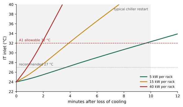
The numbers explain several design rules. With the air alone, temperatures would rise more than 10 K per minute; even with nearby mass, a high-density hall exceeds the allowable limits in a few minutes. Higher densities make this faster: the heat rises in proportion to IT load, while the air volume per kilowatt shrinks. AI halls with 100 kW racks have almost no thermal inertia on the air side, and their liquid loops (Lesson 10) heat at several kelvin per minute when their heat rejection stops.
Redundancy configurations
Redundancy provides more capacity than the load needs, so that units can fail or be maintained without loss of cooling:
- N: exactly enough capacity, no spare. Any failure or maintenance reduces capacity.
- N+1, N+2: one or two spare units of the same type. Common for chillers, pumps, CRAHs and CDUs.
- 2N: two complete, independent systems, each able to carry the full load. Expensive, but protects against failures of a whole system, including piping and controls.
- Distributed or shared redundancy: a pool of units serves several zones, with spare capacity shared.
The value of redundancy depends on how independent the units are. If failures are independent, the probability that too many units fail at once falls dramatically with each spare:
from math import comb

# Probability that too few cooling units are working, each available with probability a
def short(k, n, a):
    return sum(comb(n, i) * a ** i * (1 - a) ** (n - i) for i in range(0, k))

a = 0.995                      # each unit available 99.5% of the time, failures independent
need = 8
for name, n in (("N (no spare)", need), ("N+1", need + 1), ("N+2", need + 2), ("2N", 2 * need)):
    p = short(need, n, a)
print(f"{name:13s} {n:2d} units: P(short of capacity) = {p:.1e}, about {8760 * p:.2g} h per year")N (no spare) 8 units: P(short of capacity) = 3.9e-02, about 3.4e+02 h per year N+1 9 units: P(short of capacity) = 8.8e-04, about 7.7 h per year N+2 10 units: P(short of capacity) = 1.5e-05, about 0.13 h per year 2N 16 units: P(short of capacity) = 2.2e-17, about 1.9e-13 h per year
In this idealized calculation, one spare reduces shortfall from hundreds of hours a year to a few, and 2N makes it negligible. Real systems fall short of these numbers because failures are not independent.
Common-mode failures
A common-mode failure disables several supposedly redundant components at once. In cooling systems the usual culprits are:
- Shared power: all chillers on one electrical bus, or pumps and controls without UPS, so a single power event stops everything.
- Shared piping: a single header, valve or heat exchanger through which all redundant units' water passes; a leak or a valve failure stops them all.
- Shared controls: one controller, network switch or sensor that every unit depends on, or a software change that affects all units together.
- Shared environment: all heat rejection on one roof exposed to the same snow, ice, hail, wildfire smoke or debris; cooling towers on a single make-up water supply.
- Human error: a maintenance procedure applied to all units, or an operator closing the wrong valve.
Designs address these through separation (redundant units on separate power, piping paths and control nodes), concurrent maintainability (any component can be removed for maintenance without stopping cooling), and procedures that make errors less likely. The Uptime Institute Tier classification and TIA-942 rating levels (DCE-200) express these principles: concurrently maintainable designs (Tier III) and fault-tolerant designs (Tier IV) require redundant distribution paths, not just redundant units.
Worked problem
Finding the single point of failure
A plant has three chillers (N+1) and three pumps (N+1), all connected to a single supply header with one motorized isolation valve leading to the data hall. Each chiller and pump is on a separate electrical feed. What single failure can stop all cooling, and how is it fixed?
Show solution
- The single header and its isolation valve carry all chilled water to the hall.
- A leak in that header, or the valve failing closed, stops flow regardless of chiller and pump redundancy.
Answer: The header and valve are a single point of failure. Fixes: a looped header or a second supply path with its own valves, and valves that fail in place (or open) rather than closed, so one valve cannot isolate the hall.
Power interruptions and restart
Most data centres keep IT equipment running on UPS through utility interruptions while generators start (DCE-310). Cooling is more complicated:
- Chillers usually stop on a power interruption and need several minutes to restart, longer if a restart is attempted before internal pressures equalize.
- Fans and pumps can restart in seconds on generator power, and are often on UPS so that air and water keep moving during the transfer.
- Controls must be on UPS so they remember their state and manage the restart sequence.
Thermal ride-through bridges the gap. Chilled-water storage tanks, or the stored cold in a large chilled-water loop, keep supplying cold water while chillers restart, provided pumps and air handlers keep running. The code example above found about 34 m³ of storage for 10 minutes at 2 MW. For liquid-cooled racks, CDU pumps on UPS and facility water storage play the same role.
Worked problem
Restart sequence
After a utility outage, generators come online in 15 s. The plant has three chillers. Why are the chillers restarted one at a time rather than together?
Show solution
- Each chiller compressor draws a large starting current; starting all three together could overload the generators or cause voltage dips that trip other loads.
- Staggering by about 30 s to 60 s keeps the generator within its capability.
Answer: To limit inrush on the generators. The restart sequence, coordinated between electrical and mechanical controls, is a critical part of design and must be tested with the real generators.
Testing and commissioning
Designed redundancy is only real if it works when needed. Commissioning verifies this before the facility opens, in levels:
- Factory witness tests of major equipment (chillers, CDUs, air handlers).
- Installation checks and start-up of each component.
- Functional tests of each system and its controls.
- Integrated systems tests: the whole facility under simulated IT load from load banks, with failures introduced deliberately: a chiller tripped, a pump stopped, a valve closed, utility power cut, while IT inlet temperatures are monitored. The test confirms that redundancy, controls and ride-through work together.
Load banks that produce heat like IT equipment (air-cooled banks, and liquid-cooled load banks for CDU loops) make such tests possible before tenants move in. Testing at partial load as well as full load reveals control instabilities that appear only at low load.
Maintenance and operations
Over the life of a facility, reliability depends on operations:
- Preventive maintenance on schedules from manufacturers and standards: coil cleaning, filter changes, bearing lubrication, belt and fan inspection, water treatment, valve exercising, sensor calibration.
- Predictive maintenance: vibration analysis on pumps and fans, thermography of electrical connections, oil analysis on chillers, trending of approach temperatures that reveal fouling.
- Method of procedure (MOP) documents for every maintenance activity on critical systems, listing steps, checks and back-out plans, reviewed and approved before work.
- Emergency operating procedures for cooling failures: what to check, which valves to operate, when to shed IT load. Operators drill them.
- Post-incident reviews that find root causes, including contributing factors in design, procedures and training.
Worked problem
Maintenance and redundancy
A plant has N+1 chillers. One chiller is taken out for a two-day overhaul in summer. What is the plant's redundancy during the work, and how is the risk managed?
Show solution
- With one chiller out, the plant runs at N: no spare capacity.
- Any further chiller failure during the overhaul would cause a shortfall.
Answer: Redundancy is N during the work. Risk is managed by scheduling major work in cool weather (when economizers or lower loads provide margin), arranging temporary chillers if needed, verifying the remaining units beforehand, and shortening the outage. This is why N+2 or 2N designs are chosen where maintenance must be done at any time.
Common mistakes
MistakeAssuming thermal mass gives operators plenty of time.
InsteadHigh-density halls exceed limits within minutes; automate responses and provide ride-through.
MistakeCounting redundant units without checking shared paths.
InsteadLook for common-mode failures in power, piping, controls and environment.
MistakePutting fans and pumps on generator only.
InsteadKeep fans, pumps and controls on UPS so stored cold can reach the IT load.
MistakeSkipping integrated systems testing.
InsteadTest failures under load before go-live, including power loss and restart.
MistakeDoing critical maintenance without a written procedure.
InsteadUse reviewed MOPs with back-out plans.
Summary and key terms
- After loss of cooling, temperatures rise at P/C; dense halls reach limits in minutes.
- N+1, N+2 and 2N redundancy reduce shortfall probability dramatically if failures are independent.
- Common-mode failures in power, piping, controls, environment and human action defeat redundancy.
- Thermal storage and UPS-backed pumps and fans ride through chiller restarts.
- Commissioning culminates in integrated systems tests with simulated load and induced failures.
- Maintenance, MOPs, emergency procedures and incident reviews sustain reliability.
- Redundancy
- Capacity beyond what the load requires.
- N+1
- The required number of units plus one spare.
- 2N
- Two complete independent systems, each able to carry the load.
- Common-mode failure
- A single cause that disables several redundant components.
- Single point of failure
- A component whose failure alone stops the system.
- Concurrent maintainability
- The ability to maintain any component without interrupting cooling.
- Thermal ride-through
- Continuing to cool from stored cold while equipment restarts.
- Integrated systems test
- A facility-wide test under load with induced failures.
- Load bank
- Equipment that produces a controllable electrical and heat load for testing.
- MOP
- Method of procedure for maintenance on critical systems.
Practice problems
Work each problem on paper first, then reveal the answer to check.
Temperature rise rate for 1 MW into 30,000 kJ/K?
Show answer
0.033 K/s, 2 K/min.
Why do high-density halls heat faster after cooling loss?
Show answer
More heat per unit of air and thermal mass.
Storage for 8 min at 1.5 MW with 8 K ΔT (ignore mixing losses)?
Show answer
1,500 × 480/(4.18 × 1000 × 8) ≈ 21.5 m³.
What must stay powered for stored cold to help?
Show answer
Pumps, fans and controls.
Give three sources of common-mode failure.
Show answer
Shared power, shared piping, shared controls (also environment, human error).
What redundancy remains in an N+1 plant with one unit in maintenance?
Show answer
None (N).
Why stagger chiller restarts on generator power?
Show answer
To limit inrush current on the generators.
What does an integrated systems test include?
Show answer
Full facility under simulated load with induced failures.
What is a MOP?
Show answer
A written method of procedure for critical maintenance.
Why might a single isolation valve defeat N+1 chillers?
Show answer
All flow passes through it; its failure stops cooling.
Lesson quiz · 5 questions
Score 60% or more to complete this lesson.
Create a free account to save your progress, take quizzes and earn a certificate.