
DCE-330 · Lesson 1 of 12 · 34 min
Heat loads and ASHRAE thermal guidelines
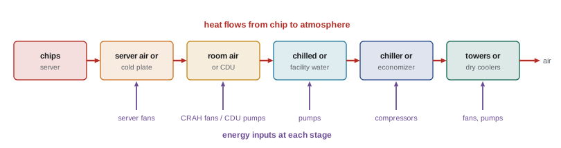
Every watt of electricity delivered to a server becomes a watt of heat. A data hall drawing 20 MW of IT power is, thermodynamically, a 20 MW heater, and the cooling system's job is to carry that heat from the chips, through air or liquid, out of the building and into the atmosphere, a river or a district heating network, continuously and with redundancy, at the lowest practical energy and water cost. Cooling is usually the largest consumer of energy in a data centre after the IT equipment itself, and with AI racks now exceeding 100 kW each, it has become the main constraint on how dense a facility can be.
This course follows the heat along that path. This lesson quantifies heat loads and sets the environmental limits that the IT equipment needs. The section at the end of this lesson maps the rest of the course. The course builds on the thermodynamics and heat transfer of MEC-340.
Where the heat comes from
The heat load of a data hall is the sum of:
- IT equipment: essentially all its electrical input becomes heat in the room, apart from a negligible amount leaving as network signals. This is by far the largest component.
- Power distribution losses inside the space: UPS systems, transformers, PDUs and busway that sit in or near the hall lose a few percent of the power they carry as heat.
- Lighting, people and the building envelope: small in a large hall (lighting perhaps 5 to 10 W/m², a person about 100 W, and solar and conduction gains through walls and roof), but not negligible in small rooms.
- Fans in the cooling equipment itself, whose power is also turned into heat in the airstream.
Designers express load in kilowatts (kW) or megawatts. In North American mechanical practice, cooling capacity is also given in tons of refrigeration and BTU per hour:
A 1 MW hall therefore needs about 284 tons of cooling, before any margin or redundancy.
Density
Load is described per rack and per unit of floor area. Typical enterprise racks drew 3 to 8 kW for many years, and much existing cooling equipment was designed around that. Cloud racks reached 10 to 20 kW, and racks of AI accelerators now range from about 40 kW to well above 100 kW: a single rack of current GPU servers can dissipate 120 kW or more. Density matters because air can only carry so much heat through a rack-sized opening at reasonable speeds and noise levels; beyond roughly 30 to 50 kW per rack, liquid cooling becomes necessary (Lesson 9).
Worked problem
Hall cooling load
A hall has 400 racks at an average of 12 kW, plus 30 racks of network and storage at 6 kW. Distribution losses in the hall are 3% of the IT load, lighting is 8 W/m² over 2500 m², and fan heat from the cooling units is 4% of the IT load. Find the total load in kW and tons.
Show solution
- IT: \(400 \times 12 + 30 \times 6 = 4800 + 180 = 4980\) kW.
- Distribution losses: \(0.03 \times 4980 = 149\) kW. Fans: \(0.04 \times 4980 = 199\) kW. Lighting: \(8 \times 2500 = 20\) kW.
- Total: \(4980 + 149 + 199 + 20 = 5348\) kW.
- In tons: \(5348/3.517 = 1521\) tons.
Answer: About 5.35 MW, or 1520 tons. The IT load is 93% of the total; the remaining 7% is often forgotten in early estimates.
Carrying heat with air and water
Heat is carried by a fluid flow according to the sensible heat equation, \(\dot Q = \dot m c_p \Delta T\). For air at typical conditions (density about 1.2 kg/m³, specific heat 1.006 kJ/kg·K), and for water (1000 kg/m³, 4.19 kJ/kg·K), this becomes:
In inch-pound units the equivalent working formulas are \(\dot Q\,[\text{BTU/h}] = 1.08 \times \text{CFM} \times \Delta T\,[°\text{F}]\) for air and \(500 \times \text{GPM} \times \Delta T\,[°\text{F}]\) for water. The factor of about 3500 between them (per unit volume, water carries 3500 times as much heat as air for the same temperature rise) is the fundamental reason liquid cooling is so much more compact.
Worked problem
Airflow for a rack
A 15 kW rack has servers that raise the air temperature by 12 K from inlet to exhaust. What airflow does it need, in m³/s and CFM? What would a 120 kW rack need?
Show solution
- \(\dot V = \dot Q/(1.21\,\Delta T) = 15/(1.21 \times 12) = 1.03\) m³/s.
- In CFM: \(1.03 \times 2119 = 2190\) CFM (check: \(15 \times 3412/(1.08 \times 21.6) = 2190\) CFM, since 12 K = 21.6 °F).
- 120 kW: \(120/(1.21 \times 12) = 8.26\) m³/s, or about 17,500 CFM through one rack.
Answer: About 1.0 m³/s (2200 CFM) for 15 kW. For 120 kW, 8.3 m³/s through a 600 mm wide rack would mean air speeds and fan power that are impractical, which is why such racks are liquid cooled.
Worked problem
Water flow for the same heat
How much water flow carries 120 kW with a 10 K temperature rise?
Show solution
- \(\dot V = 120/(4.19 \times 10) = 2.86\) L/s (about 45 US gal/min).
Answer: About 2.9 L/s, which fits through a pipe of about 40 mm (1½ in) diameter, compared with 8.3 m³/s of air.
The ASHRAE thermal guidelines
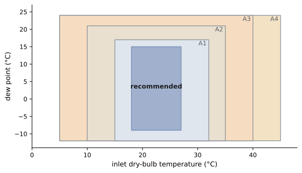
IT equipment needs inlet air within certain limits of temperature and humidity. In North America and much of the world, these limits come from ASHRAE Technical Committee 9.9, which publishes the Thermal Guidelines for Data Processing Environments (the 5th edition appeared in 2021). The guidelines define a recommended envelope, within which equipment should operate for best reliability and efficiency, and several allowable classes, within which equipment may operate for limited periods or with some reliability trade-off.
| Envelope | Dry-bulb inlet temperature | Typical use |
|---|---|---|
| Recommended (A1–A4) | 18–27 °C (64.4–80.6 °F) | Normal operating target |
| Recommended (H1, high-density) | 18–22 °C (64.4–71.6 °F) | High-density equipment rated for class H1 |
| Allowable A1 | 15–32 °C (59–89.6 °F) | Enterprise servers and storage |
| Allowable A2 | 10–35 °C (50–95 °F) | Volume servers, most modern IT |
| Allowable A3 | 5–40 °C (41–104 °F) | Equipment rated for wider limits |
| Allowable A4 | 5–45 °C (41–113 °F) | Equipment rated for widest limits |
The guidelines also limit moisture. In the recommended envelope the dew point is between −9 °C and 15 °C, with relative humidity at or below 70% (or 50% where gaseous pollutants are present), because high humidity combined with corrosive gases such as sulphur compounds accelerates corrosion of circuit boards. Very dry air raises the risk of electrostatic discharge, but research sponsored by ASHRAE showed the risk to be low with normal grounding practices, which allowed the lower humidity limit to be relaxed and saves the energy once spent humidifying data halls. The temperature must also not change too quickly: the guidelines limit the rate of change to 20 °C in an hour, and to 5 °C in an hour for equipment with tape drives.
Note that these limits apply to the air entering the IT equipment, not to the room average or the return air. A hall can have an average temperature of 24 °C and still have servers ingesting 35 °C air where hot exhaust recirculates; that is why sensors are placed at rack inlets and why airflow management (Lesson 3) matters so much.
Why warmer is better
For decades data halls were kept at 18 to 20 °C, but running warmer has large benefits: chillers become more efficient as the temperature they must produce rises, and the number of hours when outside air or water can do the cooling without compressors (economizer hours, Lesson 7) grows sharply. ASHRAE also published guidance (the "X-factor") estimating how failure rates of volume servers change with inlet temperature. Relative to continuous operation at 20 °C, operating part of the year at higher temperatures raises failure rates modestly, and operating part of the year below 20 °C lowers them, so a facility that runs warm in summer and cool in winter can have nearly the same average failure rate as one held at 20 °C all year.
There are limits. Above about 25 to 27 °C, server fans speed up to keep components cool, and fan power rises with the cube of speed, so total facility energy can rise even as cooling-plant energy falls. Accelerators with very high power often need cooler inlet air or liquid, which is why the H1 class exists. Operators therefore choose a set point by optimizing total energy, not facility energy alone.
Worked problem
Effect of supply temperature on a chiller
A chiller's coefficient of performance (COP, cooling delivered per unit of electrical input) rises roughly 2 to 3% for each kelvin increase in chilled-water supply temperature. If the chiller has a COP of 6.0 producing 10 °C water, estimate its COP at 16 °C using 2.5% per kelvin, and the saving in compressor power for a 5 MW load.
Show solution
- COP at 16 °C: \(6.0 \times 1.025^6 = 6.0 \times 1.16 = 6.96\).
- Compressor power at 10 °C: \(5000/6.0 = 833\) kW. At 16 °C: \(5000/6.96 = 718\) kW.
- Saving: 115 kW, about 14%.
Answer: About 115 kW (14%) less compressor power, before counting the extra economizer hours that warmer water allows, which are usually worth much more.
Measuring efficiency: PUE and related metrics
Power usage effectiveness (PUE), introduced in DCE-200, is the ratio of total facility energy to IT energy over a year. Cooling is the largest contributor to the overhead above 1.0. A related metric, partial PUE (pPUE), isolates one subsystem: the cooling pPUE is (IT energy + cooling energy)/IT energy. The efficiency of a chilled-water plant is often expressed in kW of electrical input per ton of cooling:
A modern water-cooled chiller plant, including chillers, pumps and towers, may run at 0.5 to 0.7 kW/ton at design conditions and much less when economizing; an older plant may run at 1.0 kW/ton or more.
Worked problem
Cooling energy and PUE
An IT load of 8 MW is cooled by a plant averaging 0.45 kW/ton over the year, plus air handler fans of 4% of IT power. Other overheads (UPS losses, lighting) add 0.08 to the PUE. Estimate the cooling pPUE and the overall PUE.
Show solution
- Load in tons (including fan heat): \(8000 \times 1.04/3.517 = 2366\) tons.
- Plant power: \(2366 \times 0.45 = 1065\) kW; fan power: 320 kW; cooling total 1385 kW.
- Cooling pPUE: \((8000 + 1385)/8000 = 1.17\).
- Overall PUE: \(1.17 + 0.08 = 1.25\).
Answer: A cooling pPUE of about 1.17 and an overall PUE of about 1.25. Halving the plant's kW/ton through economizing and warmer water would bring the PUE close to 1.18.
ASHRAE Standard 90.4, Energy Standard for Data Centers, sets minimum efficiency requirements for the mechanical and electrical systems of data centres, expressed as maximum design annualized mechanical load components that vary with climate zone.
In Canada, energy efficiency of buildings is governed by the National Energy Code of Canada for Buildings (NECB) as adopted by each province (some provinces, such as Ontario and British Columbia, have their own energy requirements and step codes). Data centres are not treated separately in the NECB as they are in ASHRAE 90.4, but the NECB permits compliance through ASHRAE 90.1 in some provinces, and many operators adopt ASHRAE 90.4 targets voluntarily or by owner requirement.
How this course is organized
The course follows the heat from the chip to the outdoors and back to the design table. Lesson 1 covers heat loads and environmental limits, and Lesson 2 the psychrometrics of moist air. Lessons 3 and 4 cover air cooling: airflow management and containment, then the terminal units that cool the air. Lessons 5 and 6 cover chilled-water plants and heat rejection, then pumps, piping and hydronic design. Lesson 7 covers economizers, evaporative cooling and water use, and Lesson 8 controls and monitoring. Lessons 9 and 10 cover liquid cooling, first at the rack and then for whole AI halls. Lesson 11 covers reliability and failure response, and Lesson 12 annual energy, sustainability and a complete design project.
Common mistakes
MistakeSizing cooling for the IT load alone.
InsteadAdd distribution losses, fan heat, lighting and envelope gains, then redundancy and growth margin.
MistakeControlling the hall to its return air or average temperature.
InsteadASHRAE limits apply at the IT inlet; measure and control at rack inlets.
MistakeKeeping halls at 18 to 20 °C by habit.
InsteadOperate within the recommended envelope (up to 27 °C) and optimize total energy, including server fans.
MistakeHumidifying to prevent electrostatic discharge.
InsteadModern guidance allows dew points down to −9 °C with proper grounding; humidification wastes energy and water.
MistakeConfusing tons of refrigeration with tonnes of mass.
InsteadA ton of refrigeration is 12,000 BTU/h, or 3.517 kW of heat removal.
Summary and key terms
- All IT power becomes heat; add distribution losses, fan heat, lighting and envelope gains for the total load.
- 1 ton = 3.517 kW = 12,000 BTU/h; 1 kW = 3412 BTU/h.
- Air: Q[kW] ≈ 1.21 V̇[m³/s] ΔT; BTU/h = 1.08 × CFM × ΔT°F. Water: Q[kW] ≈ 4.19 V̇[L/s] ΔT; BTU/h = 500 × GPM × ΔT°F.
- Per unit volume, water carries about 3500 times the heat of air, which is why dense racks need liquid.
- ASHRAE recommended inlet envelope: 18–27 °C, dew point −9 to 15 °C, RH ≤ 70%; allowable classes A1–A4 extend to 32–45 °C; H1 for high density.
- Limits apply at the IT inlet, not the room average.
- Warmer operation improves chiller efficiency and economizer hours, until server fan power rises.
- PUE and pPUE measure overhead; plant efficiency is kW/ton = 3.517/COP. ASHRAE 90.4 sets data centre energy requirements.
- Heat load
- The total rate of heat that the cooling system must remove.
- Rack density
- The power drawn, and heat produced, per rack.
- Ton of refrigeration
- A cooling rate of 12,000 BTU/h, or 3.517 kW.
- Sensible heat
- Heat that changes a fluid's temperature without changing its phase.
- Recommended envelope
- The ASHRAE range of inlet conditions for normal operation with best reliability.
- Allowable class
- An ASHRAE range of inlet conditions (A1–A4) within which equipment may operate.
- Dew point
- The temperature at which air becomes saturated and moisture condenses.
- Inlet temperature
- The temperature of air entering IT equipment, where ASHRAE limits apply.
- COP
- Coefficient of performance: cooling delivered divided by electrical input.
- kW/ton
- Electrical input per ton of cooling, equal to 3.517/COP.
- Partial PUE
- PUE computed for one subsystem, such as cooling.
- X-factor
- ASHRAE's estimate of relative server failure rate as a function of inlet temperature.
Practice problems
Work each problem on paper first, then reveal the answer to check.
Convert 2 MW of heat load to tons and BTU/h.
Show answer
2000/3.517 = 569 tons; 2000 × 3412 = 6.82 million BTU/h.
What airflow removes 30 kW with a 15 K rise?
Show answer
30/(1.21 × 15) = 1.65 m³/s (about 3500 CFM).
Using inch-pound units, what CFM removes 10 kW with a 20 °F rise?
Show answer
10 × 3412/(1.08 × 20) = 1580 CFM.
What water flow in GPM carries 300 tons with a 10 °F rise?
Show answer
300 × 12,000/(500 × 10) = 720 GPM.
A chiller has a COP of 5.5. What is its kW/ton?
Show answer
3.517/5.5 = 0.64 kW/ton.
Why is a hall with a 24 °C average temperature not necessarily within the ASHRAE recommended envelope?
Show answer
The limits apply at each server inlet; recirculated hot exhaust can push some inlets above 27 °C while the average looks fine.
Name two reasons not to raise inlet temperatures without limit.
Show answer
Server fans speed up and their power rises with the cube of speed; high-power accelerators may need cooler inlets (class H1); reliability margins shrink.
A 3 MW IT load has 360 kW of cooling energy on average. What is the cooling pPUE?
Show answer
(3000 + 360)/3000 = 1.12.
Which ASHRAE allowable class extends to 35 °C?
Show answer
A2 (10–35 °C).
How many 300-ton chillers are needed for a 2.5 MW load with N+1 redundancy?
Show answer
2500/3.517 = 711 tons; N = 3 chillers (900 tons); N+1 = 4 chillers.
Lesson quiz · 5 questions
Score 60% or more to complete this lesson.
Create a free account to save your progress, take quizzes and earn a certificate.