
CON-240 · Lesson 2 of 12 · 33 min
Loads and load paths
A structure exists to carry loads to the ground. Every kilogram of concrete, every person on a floor, every centimetre of snow on a roof and every gust of wind against a wall creates a force that must travel through slabs, beams, columns, walls and foundations until it reaches soil or rock that can resist it. That route is the load path. If any link in it is missing, weak or not yet built, the load finds another way down, and that way may be a collapse.
This lesson explains the kinds of loads the code requires engineers to consider, how loads are combined, how they travel through a building and how to estimate the load on a member using tributary areas. These are the tools a construction manager needs to reason about construction loads, stored materials and temporary works.
Types of loads
Codes divide loads into categories because each behaves differently and carries different uncertainty.
- Dead load (D): the weight of the structure itself and everything permanently attached to it, such as floors, walls, finishes, ceilings, mechanical equipment and cladding. Dead loads are predictable because they can be calculated from dimensions and material densities.
- Live load (L): loads from occupancy and use, such as people, furniture, stored goods and movable equipment. The code specifies minimum uniformly distributed values and concentrated loads for each type of occupancy.
- Snow and rain load (S): loads from accumulated snow and the rain that soaks it, including drifts against parapets and higher roofs.
- Wind load (W): pressures and suctions from wind on walls and roofs, which push the building sideways and try to lift roofs off.
- Earthquake load (E): inertial forces produced when the ground shakes and the building's mass resists moving with it.
- Other loads: soil and water pressure on walls below grade, temperature movements, shrinkage and creep, impact from vehicles or cranes, and ice on towers.
During construction there are also construction loads: workers, equipment, stored materials, wet concrete, formwork and the impact of placing concrete or landing loads from a crane. These can be larger and more concentrated than the design live load and act on members that are not yet at full strength.
Densities and dead loads
Dead loads are calculated from the volume of each element and the unit weight of its material. A few values are worth memorizing because they come up constantly on site.
| Material | Unit weight (approximate) |
|---|---|
| Normal-weight reinforced concrete | 24 kN/m³ |
| Structural steel | 77 kN/m³ |
| Softwood lumber, dry | about 5 kN/m³ |
| Water | 9.81 kN/m³ |
| Dry sand or gravel | 16 to 19 kN/m³ |
| Concrete block wall, 190 mm, partly grouted | about 2.5 to 3 kPa of wall face |
Worked problem
Dead load of a concrete slab
A flat plate slab is 225 mm thick in normal-weight concrete. Ceilings, mechanical and partitions add an allowance of 1.5 kPa. What is the total dead load in kPa?
Show solution
- Slab self-weight: 0.225 m × 24 kN/m³ = 5.4 kPa.
- Add superimposed dead load: 5.4 + 1.5 = 6.9 kPa.
- Note how much of the total is the slab itself; this is why concrete buildings are heavy.
Answer: About 6.9 kPa.
Live loads in the code
The code gives minimum live loads for each occupancy. The values are not predictions of what is usually on a floor; they are deliberately conservative to cover crowding, storage and future changes of use. The engineer may use higher values if the owner expects heavy use.
| Occupancy (examples) | Minimum uniform live load (NBC) |
|---|---|
| Residential floors | 1.9 kPa |
| Offices | 2.4 kPa |
| Corridors above the first storey, assembly areas with fixed seats | 4.8 kPa or as specified |
| Assembly areas without fixed seats, stages | 4.8 kPa |
| Light storage | 6.0 kPa or more |
| Parking garages for cars | 2.4 kPa plus concentrated loads |
Live load reduction is allowed for members that support large areas, because it is unlikely that every square metre of a large floor area will be fully loaded at once. That is why a column supporting many floors is not designed for the full live load on every floor.
Snow, wind and earthquake: the environmental loads
In Canada, NBC Part 4 gives climatic data for hundreds of locations in Appendix C, including the ground snow load Ss and the associated rain load Sr in kPa, and hourly wind pressures. The roof snow load is calculated as S = Is[Ss(Cb Cw Cs Ca) + Sr], where Is is an importance factor, Cb a basic roof factor (often 0.8), Cw a wind exposure factor, Cs a slope factor and Ca an accumulation factor for drifts. Seismic design uses spectral accelerations from the Geological Survey of Canada's national seismic hazard model, which is highest in coastal British Columbia and parts of Quebec.
Wind pressure depends on the square of wind speed. The basic relationship is the dynamic pressure q = ½ρV², where ρ is the density of air (about 1.2 kg/m³) and V is the wind speed. Codes add factors for height, exposure, gusts and building shape, but the square law explains why a storm that doubles the wind speed quadruples the pressure on a wall.
Worked problem
Wind pressure from wind speed
Estimate the dynamic wind pressure for wind speeds of 50 km/h and 100 km/h, using ρ = 1.2 kg/m³.
Show solution
- Convert 50 km/h: 50 ÷ 3.6 = 13.9 m/s.
- q = 0.5 × 1.2 × 13.9² ≈ 116 Pa, or 0.12 kPa.
- Convert 100 km/h: 27.8 m/s.
- q = 0.5 × 1.2 × 27.8² ≈ 463 Pa, or 0.46 kPa: four times the pressure for twice the speed.
Answer: About 0.12 kPa at 50 km/h and 0.46 kPa at 100 km/h.
For construction managers the practical point is that wind on unbraced walls, formwork panels, hoarding, signs and partly built frames rises quickly in a storm. Temporary works must be designed for wind, and work plans should set wind limits for crane lifts, form handling and masonry.
Load combinations
Loads do not all reach their maximum at once. A building is unlikely to be fully occupied, under a design snow load and hit by a design windstorm at the same moment. Codes use load combinations with load factors that reflect the probability of each combination and the uncertainty in each load. Engineers check every relevant combination and design for the worst.
NBC Part 4 uses limit states design. Typical ultimate limit state combinations include 1.4D; 1.25D + 1.5L + 1.0S (or 0.5S); 1.25D + 1.5S + 1.0L (or 0.5L); and 1.25D + 1.4W + 0.5L or 0.5S, with 0.9D replacing 1.25D where dead load counteracts the other loads, and 1.0D + 1.0E + 0.5L + 0.25S for earthquake.
You do not need to run load combinations as a construction manager, but you should recognize that the numbers on drawings are often specified loads (unfactored) and that the engineer's design includes margins that are not available for unplanned construction loads.
Worked problem
Factored load on a floor
An office floor has D = 6.9 kPa and L = 2.4 kPa. Compare the combinations 1.4D and 1.25D + 1.5L.
Show solution
- 1.4D = 1.4 × 6.9 = 9.66 kPa.
- 1.25D + 1.5L = 1.25 × 6.9 + 1.5 × 2.4 = 8.63 + 3.6 = 12.2 kPa.
- The second combination governs at about 12.2 kPa factored.
Answer: 1.25D + 1.5L governs at about 12.2 kPa.
Load paths: gravity and lateral
There are two main load paths in every building. The gravity load path carries vertical loads down: from the floor deck to the joists or beams, from beams to girders, from girders to columns or walls, and from columns to foundations. The lateral load path carries wind and earthquake forces sideways: from the walls into the floor and roof diaphragms, from the diaphragms into the lateral force resisting system (shear walls, braced frames or moment frames) and down to the foundations.
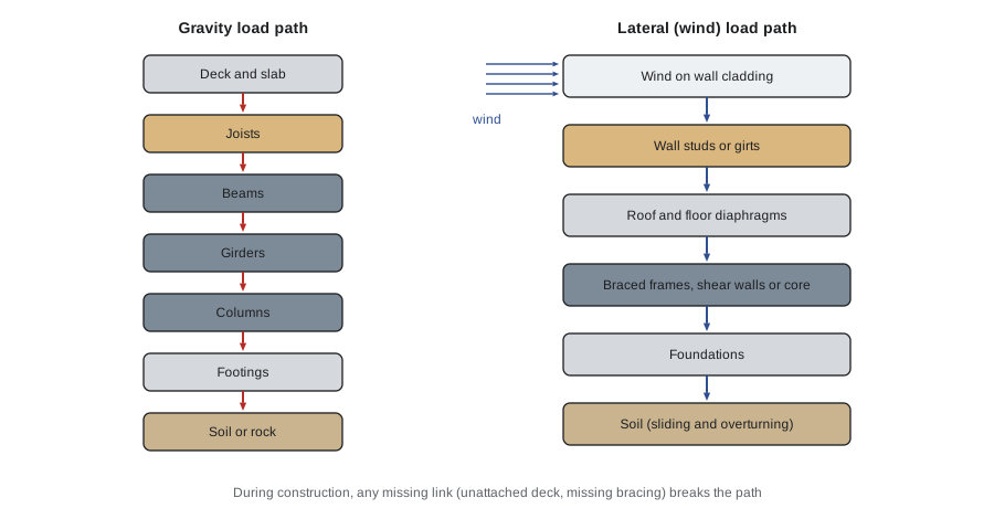
During construction, parts of these load paths are often incomplete. A steel frame may stand before its floor deck is welded, so the diaphragm that will tie it together does not yet exist. A wood-frame wall may be raised before the floor above that braces it is built. Precast panels may be set before their connections are welded. The structure in these states relies on temporary bracing to complete the load path, which is why erection sequences and bracing plans matter so much.
Tributary areas
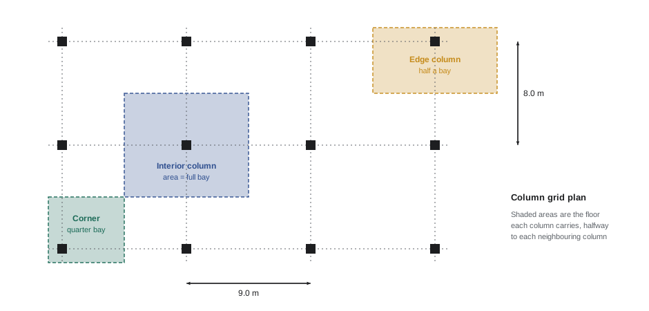
The simplest way to estimate the load on a beam or column is the tributary area method. Each member carries the load from the area of floor that is closer to it than to any neighbouring support. For a regular grid of columns, an interior column carries the area extending halfway to each adjacent column in both directions. A beam carries a strip of floor extending halfway to the beams on either side.
Worked problem
Load on an interior column
A building has columns at 8.0 m by 9.0 m spacing. Each floor has D = 6.9 kPa and L = 2.4 kPa. Ignoring live load reduction, what unfactored load does an interior column carry from one floor?
Show solution
- Tributary area: 8.0 m × 9.0 m = 72 m².
- Dead load: 72 × 6.9 = 497 kN.
- Live load: 72 × 2.4 = 173 kN.
- Total unfactored: about 670 kN per floor, plus the column's own weight.
Answer: About 670 kN per floor before live load reduction.
Worked problem
Line load on a beam
Floor beams span 9.0 m and are spaced at 3.0 m. The floor has D = 4.0 kPa and L = 2.4 kPa. What uniform line load does each interior beam carry?
Show solution
- Tributary width: 3.0 m (half a bay each side).
- w = (4.0 + 2.4) kPa × 3.0 m = 19.2 kN/m unfactored.
- The beam's own weight adds a little more.
Answer: About 19.2 kN/m.
Construction loads and why they matter
Construction loads are often more severe than service loads. When a 200 mm slab is poured, the wet concrete, the formwork, workers, vibrators, a concrete pump hose and heaped concrete all act on formwork and on the floors below through shores. When drywall is stocked, pallets can create local loads several times the design live load. A crane on a slab, or a concrete truck on a podium, imposes wheel or outrigger loads that the design may never have considered.
In Canada, CSA S269.1 sets design loads for falsework, including minimum construction live loads on formwork in addition to the weight of concrete and forms, and requires consideration of impact and lateral loads. Many engineers also refer to ASCE 37 for construction loads.
The safe approach is simple: treat any load you are about to put on a structure during construction as a question for an engineer unless it is clearly within an approved plan, such as a loading plan on the drawings or a formwork engineer's laydown limits.
Common mistakes
MistakeAssuming design live load is a capacity you can use for stored materials.
InsteadDesign live loads have margins for occupancy, not for concentrated construction loads on young concrete; get engineering approval for laydown.
MistakeForgetting that wind pressure rises with the square of speed.
InsteadDoubling the wind speed quadruples the pressure; set wind limits for lifts, form handling and unbraced walls.
MistakeIgnoring incomplete lateral load paths.
InsteadUntil diaphragms, bracing and connections are complete, the structure depends on temporary bracing designed for wind.
MistakeUsing the full floor area instead of the tributary area.
InsteadEach member carries only the area closer to it than to neighbouring supports.
MistakeMixing unfactored and factored loads.
InsteadDrawings usually give specified loads; factored loads include safety margins and are not spare capacity.
Summary and key terms
- A load path carries every load continuously from where it acts to the foundations.
- Dead loads come from material weights; live loads from occupancy; snow, wind and earthquake from climate and geology.
- Concrete weighs about 24 kN/m³, so each 100 mm of slab adds about 2.4 kPa.
- Wind pressure is proportional to the square of wind speed, q = ½ρV².
- Load combinations apply factors to each load type; designers check all combinations and use the worst.
- Tributary area estimates how much floor each beam or column supports.
- Construction loads can exceed design live loads and act on members not yet at full strength.
- Load path
- The continuous route by which loads travel through a structure to the ground.
- Dead load
- The permanent weight of the structure and fixed components.
- Live load
- Load from occupancy and use, specified as a minimum by the code.
- Snow load
- Load from accumulated snow and associated rain, including drifts.
- Lateral load
- Horizontal load from wind or earthquake.
- Diaphragm
- A floor or roof acting as a horizontal beam that collects and distributes lateral loads.
- Load combination
- A set of load types multiplied by factors that the structure must resist together.
- Load factor
- A multiplier on a specified load that accounts for uncertainty and probability.
- Tributary area
- The area of floor or roof carried by a particular member.
- Construction load
- A temporary load during construction, such as workers, equipment, materials and wet concrete.
Practice problems
Work each problem on paper first, then reveal the answer to check.
Name four load types the code requires engineers to consider.
Show answer
Dead, live, snow, wind, earthquake, soil and water pressure (any four).
What is the self-weight of a 300 mm concrete slab?
Show answer
0.3 × 24 = 7.2 kPa.
If wind speed increases from 40 to 80 units, how does pressure change?
Show answer
It quadruples, because pressure varies with the square of speed.
Columns are at 7.5 m × 7.5 m. What is the tributary area of an interior column?
Show answer
56.25 m².
An edge column on a 7.5 m × 7.5 m grid has what tributary area?
Show answer
About 7.5 × 3.75 = 28.1 m² (ignoring any cantilever).
Beams at 2.5 m spacing carry a floor of D = 4.5 kPa and L = 2.4 kPa. What is the line load?
Show answer
6.9 × 2.5 = 17.25 kN/m.
What is a diaphragm?
Show answer
A floor or roof that acts as a horizontal beam, collecting lateral loads and delivering them to shear walls or frames.
Why might a partly built steel frame need temporary bracing?
Show answer
Its floor diaphragms and permanent bracing are not yet complete, so the lateral load path is interrupted.
Which combination usually governs an office floor under gravity loads?
Show answer
1.25D + 1.5L.
Why can construction loads be more severe than service loads?
Show answer
They can be concentrated, dynamic and applied to young concrete or incomplete structures.
Lesson quiz · 5 questions
Score 60% or more to complete this lesson.
Create a free account to save your progress, take quizzes and earn a certificate.