
CON-240 · Lesson 10 of 12 · 30 min
Temporary works I: formwork, falsework and shoring
Temporary works are the structures that exist only to build the permanent structure: formwork that shapes concrete, falsework and shores that hold it up until it can support itself, reshores that share load between young floors, braces that keep walls and frames upright, and the platforms, ramps and supports that carry workers and equipment. They are designed, built and removed by constructors, they carry loads as large as the permanent structure carries, and they are often built quickly from reused components by crews under schedule pressure. Formwork and falsework failures are among the most frequent and deadly structural failures in construction. This lesson and the next cover the temporary works that constructors are directly responsible for.
Responsibility for temporary works
The engineer of record designs the permanent structure but usually not the temporary works. The contractor is responsible for the means and methods of construction, including formwork, falsework, shoring, reshoring and bracing, and must arrange their design by a competent person, typically a professional engineer for anything significant.
Good practice, adopted from the British temporary works standard BS 5975 and increasingly used in North America, assigns a temporary works coordinator on each project who keeps a register of temporary works, makes sure each item has a design, checks that the design brief reflects the actual site conditions, and gives permission to load and permission to strike (remove) only when checks are complete.
In Canada, falsework and formwork are covered by CSA S269.1 (Falsework and formwork) and, in older references, CSA S269.3 for concrete formwork; check which edition your jurisdiction references. Provincial regulations add requirements: Ontario's construction regulation (O. Reg. 213/91) has sections dealing with forms, formwork, falsework and reshoring, generally requiring design by a professional engineer for significant falsework, drawings on site, and inspection by the engineer or a competent worker before concrete is placed. Confirm the exact requirements in the current regulation for your province.
| Item | Typical designer | Typical checks before loading |
|---|---|---|
| Wall and column formwork | Formwork supplier or contractor's engineer | Ties, walers and bracing as drawn; pour rate and concrete type as assumed |
| Slab formwork and shoring | Formwork engineer | Shore spacing, plumbness, mudsills, bracing, head and base fixity |
| Reshoring | Formwork engineer | Number of reshored floors, spacing, snug installation, removal sequence |
| Falsework towers and beams | Professional engineer | Foundation, bracing, connections, settlement monitoring |
| Temporary bracing of walls and frames | Erector or bracing engineer | Anchors, brace tension, wind limits |
Loads on slab formwork
Slab formwork and shoring carry the weight of fresh concrete and reinforcing, the formwork itself, and construction live loads from workers, equipment and concrete placement, including impact and heaping. Lateral loads from wind, out-of-plumb shores and equipment must also be resisted by bracing.
CSA S269.1 and ACI 347R give minimum construction live loads for formwork. ACI 347R calls for at least 2.4 kPa of construction live load, or 3.6 kPa where motorized carts are used, and a minimum combined dead and live design load of 4.8 kPa (5.9 kPa with motorized carts). Lateral bracing is typically designed for the larger of 2 per cent of the total dead load or a specified horizontal load per metre of slab edge, plus wind.
Worked problem
Load on a shore
A 200 mm flat plate (concrete 24 kN/m³) is formed on shores at 1.2 m × 1.5 m spacing. Formwork weighs 0.5 kPa and the construction live load is 2.4 kPa. What load does each shore carry, and is a shore with a 25 kN safe working load adequate?
Show solution
- Concrete = 24 × 0.20 = 4.8 kPa.
- Total = 4.8 + 0.5 + 2.4 = 7.7 kPa.
- Tributary area per shore = 1.2 × 1.5 = 1.8 m², so load = 7.7 × 1.8 ≈ 13.9 kN.
- 13.9 kN is below 25 kN, but the safe working load drops at longer extensions; check the supplier's chart for the actual shore height.
Answer: About 13.9 kN per shore: adequate if the supplier's chart gives 25 kN at that height.
The load path through formwork is the same idea as in permanent structures: sheathing spans to joists, joists to stringers, stringers to shores, shores to mudsills, mudsills to the ground or slab below. Every link matters. Shores bearing on soft or frozen ground, unbraced tall shores, shores out of plumb, missing or loose screw-jack pins, and mixed shore types are common causes of collapse.
Lateral pressure on wall and column forms
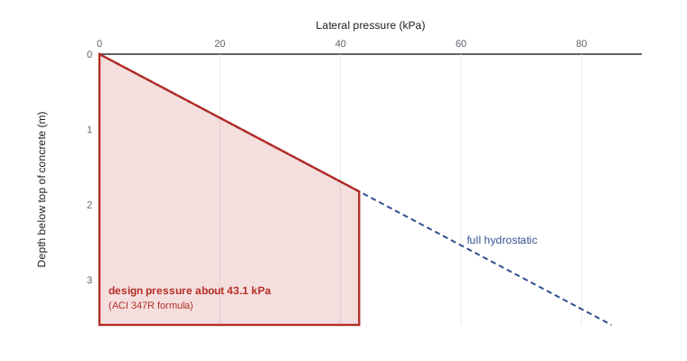
Fresh concrete behaves like a fluid at first and then stiffens as it sets. On vertical forms, it pushes sideways with a pressure that can approach full fluid (hydrostatic) pressure. The pressure depends on the rate of placement, concrete temperature, the mix (retarders, slag and fly ash slow stiffening), unit weight and vibration. Fast pours in cold weather with retarded mixes or self-consolidating concrete (SCC) produce the highest pressures.
The maximum possible pressure is full hydrostatic pressure, equal to the concrete unit weight times the depth:
ACI 347R gives a formula for walls and columns with ordinary concrete and normal internal vibration that is widely used in both countries, including in the CSA formwork standard. In SI units, for columns and for walls with a rate of placement under 2.1 m/h and height up to 4.2 m: p = Cw Cc [7.2 + 785 R ÷ (T + 17.8)] kPa, where R is the rate of placement in metres per hour and T is the concrete temperature in degrees Celsius, with a minimum of 30 Cw kPa and never more than γh. Cw and Cc are unit weight and chemistry coefficients, both 1.0 for normal-weight concrete with plain cement and no retarders.
Worked problem
Wall form pressure
A 3.6 m high wall is poured at 1.5 m/h with normal concrete at 15 °C (Cw = Cc = 1.0, γ = 23.6 kN/m³). What is the design lateral pressure?
Show solution
- Formula: 7.2 + 785 × 1.5 ÷ (15 + 17.8) = 7.2 + 35.9 = 43.1 kPa.
- Minimum is 30 kPa; full hydrostatic is 23.6 × 3.6 = 85 kPa.
- Design pressure = 43.1 kPa, reached at a depth of 43.1 ÷ 23.6 ≈ 1.8 m and constant below.
- If the pour rate doubles or the temperature drops, pressure rises; the pour plan must keep within the formwork design.
Answer: About 43 kPa.
Worked problem
Self-consolidating concrete in the same wall
The contractor switches the 3.6 m wall to SCC, placed from the top in 1 hour. What pressure should the forms be checked for?
Show solution
- SCC is normally designed for full hydrostatic pressure unless testing justifies less.
- Pressure = 23.6 × 3.6 ≈ 85 kPa, about double the 43 kPa design.
- The forms must be redesigned (more ties, stronger walers) or the pour slowed in lifts as the engineer directs.
Answer: About 85 kPa, roughly double: the forms need redesign or a slower pour.
Pour rate control on site is how this design becomes reality. The formwork drawings state the maximum pour rate and assumptions; the superintendent and pump operator must know them, the pour must be monitored, and changes to the mix, such as added retarder for hot weather or a switch to SCC, must go back to the formwork engineer.
Falsework
Falsework is the temporary structure supporting formwork for elevated concrete such as bridge decks, transfer slabs, high soffits and cast-in-place beams, and supporting other members during construction. It ranges from tall frame scaffolding towers to heavy steel beam and tower systems. Falsework may carry very large loads, may stand on soil, and may be exposed to wind and impact from traffic.
Falsework failures typically involve foundations (settlement or washout of mudsills), inadequate bracing (towers buckling), connections, overloading from concrete placement sequence, or modifications in the field that were not designed. Key controls include engineered design and drawings, inspection of the erected falsework against the drawings by the engineer or a competent person before loading, survey monitoring during the pour, and a stop-work trigger if settlement or deflection exceeds limits.
Reshoring and multi-storey construction
In multi-storey concrete construction, a newly cast floor cannot support its own weight until it has gained strength. The shores under it rest on the floor below, which is itself young, so loads accumulate through several floors. Reshoring is the practice of removing the original forms and shores from a slab, letting it carry its own weight, and then installing reshores snugly under it to share the load of the floors above with the floors below.
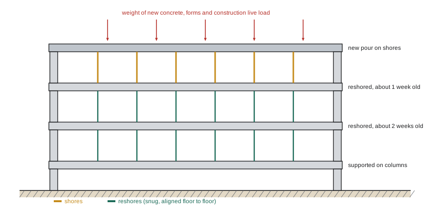
The number of floors of reshores, the time between pours and the strength of each floor determine whether any slab is overloaded. A simplified method assumes that the weight of the newest floor and its formwork is shared equally among all the slabs connected by shores and reshores. Real analyses consider relative stiffness and timing, and the formwork engineer must design the scheme.
Worked problem
Simplified reshoring check
Each slab weighs 4.8 kPa. The new pour adds 4.8 kPa of concrete, 0.5 kPa of formwork and 2.4 kPa of construction live load. Two levels of reshores connect the new pour to the three floors below. Using the equal-sharing simplification, what load does each supporting slab carry relative to its own weight?
Show solution
- Load from the new pour = 4.8 + 0.5 + 2.4 = 7.7 kPa, shared by 3 slabs: 2.57 kPa each.
- Each supporting slab carries its own 4.8 kPa plus 2.57 kPa = 7.37 kPa.
- That is about 1.5 times its own weight, applied to slabs that may be only one or two weeks old.
- The engineer compares this with each slab's capacity at its age, which is why testing and reshore schemes matter.
Answer: About 7.4 kPa, roughly 1.5 times self-weight on young slabs.
Reshoring rules on site include: install reshores snug but not jacked hard (jacking can lift and crack the slab above); install them as soon as possible after stripping; place them in the locations shown, usually aligned vertically from floor to floor; do not remove them until the engineer's criteria are met; and never stack materials on young slabs without approval.
Stripping
Stripping removes formwork and shores. Forms on vertical faces, such as wall and column sides, can usually be removed early once the concrete holds its shape, but soffit forms and shores that carry load stay until the concrete is strong enough, as covered in Lesson 5. Stripping must follow the approved sequence, which for slabs usually starts at mid-span and works toward supports so the slab is not left cantilevered, and never removes shores under post-tensioned slabs before stressing. Flying forms and table forms are moved by crane and need specific procedures for rigging and fall protection.
Common mistakes
MistakeIncreasing the pour rate or switching to SCC without telling the formwork engineer.
InsteadPressure rises sharply; get the formwork design checked for the actual pour rate and mix.
MistakeSetting shores on frozen ground or loose fill.
InsteadUse engineered mudsills on firm, protected ground, and inspect bearing before loading.
MistakeJacking reshores hard.
InsteadInstall reshores snug only; jacking lifts and cracks the slab above.
MistakeModifying falsework in the field without approval.
InsteadAny change to temporary works goes back to the designer; build to the drawings.
MistakeStacking materials on young slabs above reshores.
InsteadGet the formwork engineer's approval; young slabs may already carry 1.5 times their weight.
Summary and key terms
- Temporary works are the contractor's responsibility and must be designed, checked and controlled.
- A temporary works coordinator issues permission to load and permission to strike.
- Slab formwork carries concrete, formwork and construction live loads through a load path to the ground.
- Lateral pressure on wall forms depends on pour rate, temperature and mix; SCC is often designed as hydrostatic.
- Falsework needs engineered design, inspection before loading and monitoring during the pour.
- Reshoring shares the weight of new floors with several young floors below.
- Stripping follows strength criteria and an approved sequence.
- Temporary works
- Structures used only to build the permanent works, such as formwork, falsework and bracing.
- Formwork
- The mould that shapes fresh concrete.
- Falsework
- The temporary structure supporting formwork or members during construction.
- Shore
- A vertical temporary support under formwork or a slab.
- Reshore
- A shore installed snugly under a stripped slab to share loads from above.
- Mudsill
- A timber or plate spreading a shore load into the ground.
- Rate of placement
- The vertical rise of concrete in a form per hour.
- Hydrostatic pressure
- Fluid pressure equal to unit weight times depth.
- Permission to load
- Formal approval that temporary works may carry load.
- Stripping
- Removing formwork and shores.
Practice problems
Work each problem on paper first, then reveal the answer to check.
Who is normally responsible for the design of formwork and shoring?
Show answer
The contractor, through a competent designer such as a professional engineer.
A 250 mm slab, 0.5 kPa forms, 2.4 kPa live, shores at 1.5 m × 1.5 m. Load per shore?
Show answer
(6.0 + 0.5 + 2.4) × 2.25 ≈ 20 kN.
Full hydrostatic pressure at 3 m depth?
Show answer
23.6 × 3 ≈ 71 kPa.
What increases lateral formwork pressure?
Show answer
Faster pour rates, colder concrete, retarders, SCC and heavier concrete.
Why are reshores installed snug but not jacked?
Show answer
Jacking can lift and crack the slab above.
What is falsework?
Show answer
A temporary structure supporting formwork or members during construction.
What does a temporary works coordinator do?
Show answer
Keeps the register, checks designs and issues permission to load and strike.
Where does slab stripping usually start?
Show answer
At mid-span, working toward supports.
What minimum construction live load does ACI 347R give for slab formwork?
Show answer
2.4 kPa, or 3.6 kPa with motorized carts.
Name two common causes of shoring collapse.
Show answer
Poor mudsills or soft ground, missing bracing, out-of-plumb shores, overloading, missing jack pins.
Lesson quiz · 5 questions
Score 60% or more to complete this lesson.
Create a free account to save your progress, take quizzes and earn a certificate.