
CHE-350 · Lesson 7 of 12 · 20 min
Column hardware, sizing and energy integration
The stage count fixes a column's height; its diameter comes from hydraulics. Too much gas for the cross-section and liquid is blown up the column or backs up in the downcomers until the column floods; too little gas and liquid weeps through the tray holes without contacting the gas. Theo's next task is to size the recovery column's diameter, decide whether it should have trays or packing, and look at whether a heat pump could replace most of its steam. The last question matters most to Ingrid: the plant has committed to cutting its natural gas use, and distillation is its biggest user of steam.
Tray types
Three main tray types are in use. Sieve trays are flat plates perforated with holes typically 5 to 13 mm across; they are cheap and efficient but have a narrow operating range, because at low gas rates liquid weeps through the holes. Valve trays cover each hole with a liftable cap that closes at low gas rates, giving a wider turndown, typically 4 or 5 to 1, at a modest cost premium; they are the usual choice today. Bubble-cap trays, with a riser and cap over each hole, hold liquid even at very low gas flows and still appear in old plants and special services, but cost several times as much. Liquid crosses each tray from an inlet downcomer to an outlet weir and falls down a downcomer to the tray below; the gas rises through the openings and froths the liquid on the tray.
Flooding and the operating window
A tray column has a window of satisfactory operation. Its upper limits are entrainment flooding, where the froth reaches the tray above and liquid is carried upward, and downcomer flooding, where liquid backs up in the downcomer faster than it can drain. Its lower limits are weeping, where liquid drains through the holes, and dumping, where liquid pours through them. Between those limits the efficiency is roughly constant.
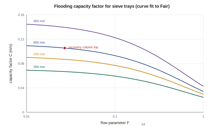
The classic method for entrainment flooding is due to James Fair (1961). It relates a capacity factor \(C\) to the flow parameter
where \(L'\) and \(V'\) are the mass flows of liquid and gas. The flooding velocity, based on the net area available for gas flow, is then
with \(\sigma\) the surface tension in mN/m. \(C\) rises with tray spacing and falls as \(F_{LV}\) increases. Designers usually aim at 70 to 85 % of flooding. The program uses a published curve fit to Fair's chart, which is approximate and suitable for screening; vendors rate final designs with their own correlations.
# Sizing the recovery column's sieve trays and estimating a heat pump
import math
# Ethanol (1) - water (2) at 1 atm: Antoine (mmHg, deg C) and van Laar constants fitted in CHE-320
ANT = {'ethanol': (8.20417, 1642.89, 230.300), 'water': (8.07131, 1730.63, 233.426)}
A12, A21 = 1.672, 0.930
def psat(c, T):  # kPa
    a, b, cc = ANT[c]
    return 10 ** (a - b / (T + cc)) * 0.133322
def gammas(x1):
    x2 = 1 - x1
    d = A12 * x1 + A21 * x2
    return math.exp(A12 * (A21 * x2 / d) ** 2), math.exp(A21 * (A12 * x1 / d) ** 2)
def bubble(x1, P=101.325):
    g1, g2 = gammas(x1)
    lo, hi = -20.0, 250.0
    for _ in range(60):
        T = (lo + hi) / 2
        s = x1 * g1 * psat('ethanol', T) + (1 - x1) * g2 * psat('water', T)
        lo, hi = (T, hi) if s < P else (lo, T)
    y1 = x1 * g1 * psat('ethanol', T) / P
    return T, y1
import math
Rg = 8.314
def fair(FLV, TS_mm, sigma):
    # curve fit to Fair's flooding chart (Lygeros and Magoulas form), C in m/s; approximate
    C = 0.0105 + 8.127e-4 * TS_mm ** 0.755 * math.exp(-1.463 * FLV ** 0.842)
    return C * (sigma / 20) ** 0.2
cases = {   # section: (molar gas flow kmol/h, gas molar mass, T K, liquid flow kg/h, rhoL, sigma mN/m)
    'top':    (32.23, 40.4, 351.6, 19.79 * 40.4, 750.0, 18.0),
    'bottom': (32.23, 18.0, 373.0, 119.79 * 18.0, 958.0, 59.0),
}
for name, (Vm, M, T, Lkg, rhoL, sig) in cases.items():
    rhoV = 101325 * M / 1000 / (Rg * T)
    Vkg = Vm * M
    FLV = (Lkg / Vkg) * math.sqrt(rhoV / rhoL)
    uf = fair(FLV, 600, sig) * math.sqrt((rhoL - rhoV) / rhoV)
    u = 0.80 * uf
    Qv = Vkg / 3600 / rhoV
    An = Qv / u                         # net area for gas flow
    At = An / 0.88                      # downcomer takes about 12 %
    D = math.sqrt(4 * At / math.pi)
    print(f"{name:6s}: gas density {rhoV:.2f} kg/m3, FLV {FLV:.3f}, flooding velocity {uf:.2f} m/s, "
          f"design {u:.2f} m/s, diameter {D:.2f} m")
# mechanical recompression of the overhead to drive the reboiler
x_top = 0.80
T1 = 78.4 + 273.15                    # overhead dew point, K
T_cond = 100 + 12 + 273.15            # must condense about 12 K above the reboiler
P1 = 101.325
P2 = P1 * psat('ethanol', T_cond - 273.15) / psat('ethanol', T1 - 273.15)
k = 1.13                               # approximate heat-capacity ratio for the ethanol-rich gas
Vm = 32.23 / 3600 * 1000               # mol/s
W_is = Vm * Rg * T1 * k / (k - 1) * ((P2 / P1) ** ((k - 1) / k) - 1) / 1000   # kW
W = W_is / 0.75
Q = 364.0                              # reboiler duty, kW
print(f"\ncompressor: {P1:.0f} -> {P2:.0f} kPa (ratio {P2 / P1:.2f}), shaft power about {W:.0f} kW")
print(f"heat delivered {Q:.0f} kW: coefficient of performance about {Q / W:.1f}")
steam_cost, power_cost = 25.0, 80.0     # illustrative: per MWh of steam heat and per MWh of electricity
print(f"hourly energy cost: steam {Q / 1000 * steam_cost:.2f}, heat pump {W / 1000 * power_cost:.2f} (illustrative prices)")top : gas density 1.40 kg/m3, FLV 0.027, flooding velocity 2.39 m/s, design 1.91 m/s, diameter 0.44 m bottom: gas density 0.59 kg/m3, FLV 0.092, flooding velocity 4.71 m/s, design 3.77 m/s, diameter 0.32 m compressor: 101 -> 337 kPa (ratio 3.33), shaft power about 45 kW heat delivered 364 kW: coefficient of performance about 8.1 hourly energy cost: steam 9.10, heat pump 3.60 (illustrative prices)
The diameter answer, and why it changes the hardware
At the top of the recovery column the gas is 80 % ethanol at 78 °C, with a density of 1.40 kg/m³, and the liquid flow is small relative to the gas: \(F_{LV} = 0.027\). The flooding velocity is 2.4 m/s; at 80 % of flooding and with 12 % of the area taken by downcomers, the diameter is 0.44 m. At the bottom the gas is steam at 0.59 kg/m³, the liquid flow is four times larger, and water's high surface tension raises the capacity: the diameter is 0.32 m. The column is sized by the larger section, so 0.44 m.
A tray column that small is impractical. Trays need access for installation and inspection, and below about 0.75 to 0.9 m diameter the tray hardware becomes awkward and the column cannot have manways for workers to enter. Small columns are almost always packed. Theo therefore switches the recovery column to random or structured packing, using the methods of CHE-314 lesson 9 for its hydraulics. With a modern structured packing, a height equivalent to a theoretical plate of 0.3 to 0.5 m is typical in this service, so 16 equilibrium stages above the reboiler need about 6 to 8 m of packing, split into two or three beds with liquid redistributors. A column of perhaps 0.5 m diameter and 12 m height including the sump, disengaging space and distributors, is a small, cheap piece of equipment.
Worked problem
Flooding velocity at the top
With \(F_{LV} = 0.027\), 600 mm tray spacing, \(\sigma = 18\) mN/m, \(\rho_L = 750\) and \(\rho_V = 1.40\) kg/m³, find \(u_{flood}\).
Show solution
- Curve fit: \(C = 0.0105 + 8.127\times10^{-4}(600)^{0.755}e^{-1.463(0.027)^{0.842}} \approx 0.106\) m/s.
- Surface tension correction: \((18/20)^{0.2} = 0.979\).
- \(\sqrt{(750 - 1.40)/1.40} = 23.1\).
- \(u_{flood} = 0.106 \times 0.979 \times 23.1 = 2.4\) m/s.
Answer: About 2.4 m/s; at 80 % of flooding, 1.9 m/s through the net area.
Trays or packing
For large columns the choice is less clear. Packing gives lower pressure drop per stage, typically a few hundred pascals per metre of structured packing against 0.5 to 1 kPa per tray, which matters in vacuum service and for heat pumps. It also holds up less liquid, which matters for heat-sensitive or hazardous materials, and suits corrosive services where packing can be made of plastic or ceramic. Trays handle high liquid rates, solids and fouling better, are easier to inspect and clean, and are more predictable at large diameters where liquid distribution over packing becomes difficult. Fermentation plants' beer columns use trays, often specially designed to tolerate solids, because beer carries yeast and grain fines. The ester line's columns, with clean liquids, are candidates for structured packing.
The energy picture
Distillation is thermodynamically inefficient. A column takes in heat at the reboiler temperature and rejects almost the same amount at the condenser temperature; the separation work it does is only a few percent of the heat that flows through it. Three families of measures recover some of that heat.
Heat integration with the rest of the plant uses the condenser's heat elsewhere, for instance to preheat a feed or to warm a fermenter, or supplies the reboiler from a hot process stream. Multi-effect distillation runs two columns at different pressures, so that the condenser of the high-pressure column boils the reboiler of the low-pressure one; the main beer column and rectifier at many ethanol plants are integrated this way, with the beer column under vacuum. Heat pumps raise the temperature of the condenser heat so that it can drive the reboiler.
A heat pump on the recovery column
The overhead gas condenses at about 78 °C; the reboiler needs heat at 100 °C. Mechanical vapour recompression compresses the overhead so that it condenses at a temperature high enough to boil the bottoms, here taken as 112 °C to give a 12 K driving force across the reboiler. The program estimates the pressure ratio from the ethanol vapour pressure at the two temperatures, 3.3, and the compressor power from an isentropic calculation with 75 % efficiency: about 45 kW. That 45 kW of electricity moves 364 kW of heat, a coefficient of performance of about 8.
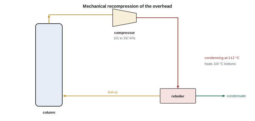
At illustrative prices, the heat pump's electricity costs about 3.60 per hour against 9.10 for steam. The savings must pay for a compressor that handles a flammable vapour, explosion-protected motors and controls, and the start-up steam reboiler that is still needed. Heat pumps are most attractive when the temperature lift is small, as in columns separating close-boiling components, because the compressor power rises steeply with the pressure ratio. Ethanol-water, with a 22 K difference between top and bottom, is at the upper end of what is usually economic. The carbon case also depends on the grid: electricity in Ontario has a different emissions intensity from the natural gas that makes the plant's steam, and Wren Halvorsen asks Theo to report both the cost and the emissions result so the comparison is fair.
Theo's recommendation
For the recovery column, Theo recommends a 0.5 m packed column with a steam reboiler now, and a note that the overhead is a candidate for recompression if the plant later installs a larger heat-pump system serving several columns. A single 45 kW compressor on a small column rarely justifies its engineering and maintenance; a combined system on the main distillation train might. Ingrid agrees, and adds the heat-pump option to the plant's decarbonization study list.
Common mistakes
MistakeSizing the column at the section with the smaller diameter.
InsteadSize each section and use the larger diameter, or use different diameters if justified.
MistakeSpecifying trays for a 0.4 m column.
InsteadSmall columns are packed; trays need access and become awkward below about 0.8 m.
MistakeDesigning at 100 % of flooding.
InsteadDesign at about 70 to 85 % of flooding to allow for uncertainty and turndown.
MistakeAssuming a heat pump always saves money.
InsteadIts benefit falls sharply as the temperature lift grows; check capital, safety and grid emissions.
Summary and key terms
- Tray columns operate between flooding and weeping limits.
- Fair's method relates a capacity factor to the flow parameter to give the flooding velocity.
- The recovery column needs only 0.44 m diameter, so it should be packed rather than trayed.
- Packing gives lower pressure drop and hold-up; trays handle fouling, solids and large diameters better.
- A recompression heat pump could deliver the 364 kW reboiler duty for about 45 kW of electricity.
- Flooding
- Excessive liquid hold-up caused by too much gas or liquid flow, ending stable operation.
- Weeping
- Liquid draining through tray openings at low gas rates.
- Flow parameter
- The liquid-to-gas mass flow ratio corrected by the square root of the density ratio.
- Turndown
- The ratio of maximum to minimum satisfactory throughput.
- Mechanical vapour recompression
- Compressing a column’s overhead so it can condense in the reboiler.
- Multi-effect distillation
- Columns at different pressures, with one condenser driving another reboiler.
Practice problems
Work each problem on paper first, then reveal the answer to check.
Compute \(F_{LV}\) at the bottom: 2,156 kg/h of liquid, 580 kg/h of gas, densities 958 and 0.59 kg/m³.
Show answer
\((2156/580)\sqrt{0.59/958} = 3.72 \times 0.0248 = 0.092\).
Why does larger tray spacing allow higher gas velocity?
Show answer
The froth has more height before it reaches the tray above.
Roughly how much packing do 16 stages need at an HETP of 0.4 m?
Show answer
About 6.4 m.
Why are beer columns trayed?
Show answer
Beer carries solids and fouls, which packing tolerates poorly.
What limits the economics of a heat pump on a column?
Show answer
The temperature lift, which sets the pressure ratio and compressor power.
How does a double-effect arrangement save energy?
Show answer
The high-pressure column’s condenser boils the low-pressure column’s reboiler.
Lesson quiz · 5 questions
Score 60% or more to complete this lesson.
Create a free account to save your progress, take quizzes and earn a certificate.