
BAS-410 · Lesson 4 of 12 · 22 min
Point-to-point checkout
▶ Video coming soon A video version of this lesson is on the way.
Callie already knew point-to-point checkout. She had done one on Wednesday, November 11, on Ninefield's RTU-1: a 23-line sheet, three faults found and fixed, Prakash's signature below her initials. Marlow Lane's checkout was the same job at a larger scale, done in an occupied building, and part of a commissioning process with someone checking the checkers. Ivo opened the binder at the checkout tab, where the sheets for 232 physical points sat behind a one-page summary. "Same method as RTU-1," he said. "The difference is that Philippa reads every sheet, and she witnessed a sample of points herself."
What point-to-point checkout proves
Point-to-point checkout proves that every physical point works from the field device, through the wiring and the controller, to the value or command the operator sees on the front end. It is done by the controls contractor, after the pre-functional checklist and before functional testing. In BAS-210's terms it follows the pre-power checks and comes before startup under the new controls, although on a replacement like Marlow Lane the equipment was already running and the checkout happened as each piece was cut over.
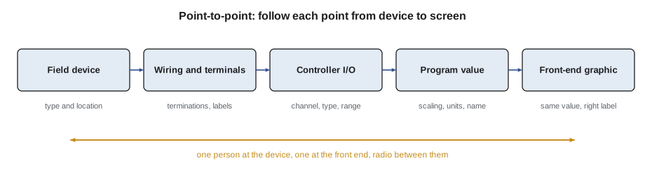
The point must be right at every link. A sensor can be wired correctly to the wrong input. A correct input can be scaled wrongly in the program. A correct value can appear on the graphic under the wrong label, or on the wrong floor plan. Checking the value only at the controller misses the last two; checking it only on the graphic hides where a fault is. A good checkout looks at both ends and records the result.
| Point type | How it is checked | Typical acceptance |
|---|---|---|
| Analog input (temperature, pressure, flow, humidity) | Compare the BAS reading with a calibrated reference instrument at the sensor; for pressure and flow, check zero and one other value | Temperature within 0.5 K (1 °F) (Quillon's sheet; some specifications are tighter); others per the specification |
| Digital input (status, alarm, switch) | Make the real change: start the fan, trip the switch, open the contact; watch the BAS change state | Correct state, correct delay, correct alarm |
| Analog output (valve, damper, speed) | Command 0, 50 and 100; observe the device move and measure the signal; time a full stroke | Device position matches the command; direction correct; stroke time recorded |
| Digital output (start, enable, stage) | Command on and off; observe the equipment respond | Correct equipment responds; nothing else does |
| Network point (from another controller or system) | Change the value at its source; watch it update | Value and units correct; update within the expected time; failure shown when communication is lost |
Marlow Lane's points
Of Marlow Lane's 445 points, 232 were physical inputs and outputs that needed a point-to-point check. The other 213 were software points (setpoints, modes, calculated values, alarms and network values) that were checked in the program review, the graphics review and the functional tests.
| System | Physical points | How Ivo grouped the work |
|---|---|---|
| VAV boxes | 180 (36 boxes × 5: zone temperature, discharge air temperature, airflow, damper, reheat valve) | One floor of 12 boxes each cutover night, with the box checklists |
| AHU-1 | 28 | Two days after the AHU-1 checklist items were fixed |
| Heating plant | 16 | With the boiler service technician present |
| Exhaust fans | 4 | With AHU-1 |
| Miscellaneous (server room unit, water heater, outdoor sensors) | 4 | With AHU-1 |
| Total | 232 |
Worked problem
Estimating the checkout
Ivo estimated about 4 minutes per VAV box point, because the box points are simple and repeated, and about 8 minutes per point on AHU-1, the plant and the other equipment, because each one needs equipment running or a reference reading in a different place. Estimate the checkout time.
Show solution
- VAV points: 180 × 4 = 720 minutes.
- Other points: 232 − 180 = 52; 52 × 8 = 416 minutes.
- Total: 720 + 416 = 1,136 minutes = 18.9 hours.
Answer: About 19 hours, which is the line in Quillon's commissioning estimate. The actual time was about 22 hours, mostly because of two third-floor boxes whose problems took over an hour each to find.
Checking inputs
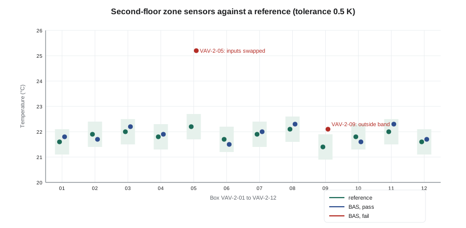
Analog inputs are checked against a reference instrument: a calibrated digital thermometer, manometer or airflow hood, whose calibration certificate is current and recorded on the sheet. Ivo's rule was to hold the reference probe at the sensor, wait for both readings to settle, and record both numbers, not just a tick.
Worked problem
A zone sensor outside tolerance
On VAV-2-09, the reference thermometer read 21.4 °C and the BAS 22.1 °C. Quillon's checkout tolerance for zone temperature is 0.5 K. Pass or fail, and what next?
Show solution
- Error: 22.1 − 21.4 = 0.7 K.
- 0.7 K is more than 0.5 K, so the point fails.
- Before adding an offset, check why: the sensor was on an outside wall above a radiator outlet, and its back box was open to the wall cavity.
Answer: Fail. Ivo sealed the back box with a foam gasket, which brought the error to 0.2 K (0.4 °F), and recorded the cause and the recheck. An offset in the program would have hidden a draft problem that changes with the weather.
Second floor box VAV-2-05 was the other failure on that chart. Its zone reading was 3 K (5 °F) above every other sensor on the floor, and its discharge air reading was close to room temperature. The two sensors had been landed on each other's inputs. That is a classic point-to-point find, the same kind of swap as Ninefield RTU-1's return air and zone sensors, and invisible on the graphic because both values looked like plausible temperatures.
Digital inputs are checked by making the real change. For AHU-1's supply fan status, Ivo started the fan and watched the status go on, then stopped it and watched it go off, recording the delay. For the exhaust fan current switches, he also checked that the switch did not show the fan running with the motor powered but the fan not turning. Exhaust fan EF-2's switch was set so low that it showed running with the fan's wheel stopped; he raised the setting and rechecked.
Checking outputs
Analog outputs are commanded to 0, 50 and 100, and someone at the device confirms the position. The signal is also measured at the device terminals, so that a wrong position can be traced to either the signal or the actuator.
Worked problem
Checking a valve signal
A VAV reheat valve actuator takes a 2 to 10 V signal. Ivo commands the output to 50. What voltage should he measure at the actuator, and what does it tell him if the valve is fully closed?
Show solution
- The span is 10 − 2 = 8 V.
- At 50: 2 + 0.5 × 8 = 6.0 V.
- If he measures 6.0 V and the valve is closed, the signal is right and the problem is at the valve: a reversed actuator, a direct or reverse acting setting, or a linkage.
Answer: 6.0 V. On two Marlow Lane boxes the valve was fully open at 0 and closed at 100: the actuators' direction switches were set to reverse. Ivo reset them, rechecked at 0, 50 and 100, and noted it on the sheet.
Stroke time is recorded for every modulating actuator, as BAS-210 described for RTU-1's economizer (92 s opening and 91 s closing, 18 s spring return). Stroke times matter later: they are used to set the loop tuning and the program's actuator timing, and a slow stroke can show a sticking damper.
Digital outputs are commanded on and off. The observer confirms that the right equipment responds and that nothing else does. On the heating plant, the boiler 2 enable output started boiler 1. The two enable wires had been swapped in the plant panel. The boiler service technician confirmed both boilers' own safeties and firing were unaffected; Ivo swapped the wires and rechecked both outputs.
What the checkout found
Marlow Lane's point-to-point checkout found 11 deficiencies in 232 points, about 5 in 100. Each one was logged in the issues log, fixed and rechecked, and the sheets show both the first result and the recheck.
| Points | Deficiency | Found by | Fix |
|---|---|---|---|
| VAV-2-05 zone and discharge sensors | Landed on each other's inputs | Sensor reading against reference | Re-landed; rechecked |
| VAV-2-09 and two other zone sensors | Outside tolerance | Reference thermometer | Back boxes sealed on two; one sensor replaced |
| Two VAV reheat valves | Actuators set to reverse | Commanding 0, 50, 100 | Direction switches reset |
| VAV-1-09 damper | Actuator rotation set wrong; damper closed when commanded open | Commanding 0, 50, 100 | Rotation reset; airflow rechecked |
| AHU-1 return fan speed feedback | Scaled for 50 Hz at full scale instead of 60 Hz | Comparing BAS speed with the drive display | Scaling corrected in the program |
| Boiler 1 and 2 enables | Swapped in the plant panel | Commanding each output | Wires swapped; both rechecked |
| EF-2 status | Current switch set too low | Running motor with wheel stopped | Setting raised; rechecked |
| Outdoor air humidity | 0 to 5 V sensor on an input configured for 0 to 10 V; read about half the real value | Comparing with a reference hygrometer | Input configuration corrected |
Ivo had a view about that 5 in 100. A clean checkout with no deficiencies on a job this size would make him suspicious, not proud. The faults are always there; the question is whether the checkout finds them or a tenant does.
Witnessing and the sheet
On a commissioned job, the commissioning provider reviews the completed checkout sheets before functional testing starts, and often witnesses a sample of points. Philippa read every Marlow Lane sheet and witnessed 24 points herself, about 1 in 10, picked across the building: several on each floor, the AHU-1 safeties and economizer, and both boiler enables. She found one sheet where a stroke time had been left blank and asked for it to be filled in, and otherwise accepted the checkout.
The sheet format was the same as Callie's RTU-1 sheet: point name, terminal, device, test, expected result, observed result, pass or fail, initials and date. Marlow Lane's sheets added one column for the reference instrument's serial number, because Philippa's plan required it. Each sheet was signed by the person who did the checks and countersigned by Philippa after her review.
Checkout sheet - VAV-2-09 (extract)
Point      Terminal  Test                          Expected       Observed        Result  Init  Date
ZN-T       UI1       ref thermometer (SN 40817)    within 0.5 K   +0.7 K          FAIL    IB    Oct 1
                     back box sealed, recheck      within 0.5 K   +0.2 K          PASS    IB    Oct 1
DA-T       UI2       ref at coil outlet            within 0.5 K   +0.1 K          PASS    IB    Oct 1
FLOW       AI        TAB to calibrate (lesson 7)   reads, zero    0 L/s at zero   PASS    IB    Oct 1
DMPR       AO1       0 / 50 / 100, stroke          moves, CW open 0/50/100, 95 s  PASS    IB    Oct 1
HW-V       AO2       0 / 50 / 100, 2-10 V          6.0 V at 50    6.0 V, opens    PASS    IB    Oct 1
Leaving every point in automatic
A checkout leaves outputs in manual and inputs overridden as it goes. Before leaving each night, Ivo ran the front end's override report and released everything he had touched, the same check Callie had done on RTU-1. On an occupied building, a box left in manual at 100 heating would have been the first complaint the next morning. On one night the report showed a point Ivo had not touched: a third-floor box left in manual by the old controls' service contractor years before, faithfully carried across in the database conversion. He released it and logged it, because it meant the old sequences had been running with a manual override nobody remembered.
Software points and the graphics check
The 213 software points were not left unchecked. Setpoints, limits and modes were checked against the sequence in a program review: Sophie and Ivo read each controller's settings against the specification's table of adjustable values. Alarm points were checked when the burn-in week sent them to Ivo. The graphics were checked page by page by walking each point from the controller to the screen: right value, right units, right label, right floor, and a link that opened the right system page. On the third-floor plan, two box labels were transposed, which no field check would ever have found. Checkout is the place to find that kind of fault, because once operators start using the graphics, they trust them.
Common mistakes
MistakeRecording a tick instead of the readings.
InsteadWrite down both the reference and the BAS reading, so a reviewer can see how close it was and so later drift can be compared.
MistakeFixing a sensor error with a program offset without finding the cause.
InsteadFind out why it is wrong first: location, drafts, wiring, wrong type. An offset is for a known, stable sensor error, not a draft.
MistakeChecking outputs only at the front end.
InsteadSomeone must see the device move, and the signal should be measured, so that a fault can be traced to the signal or the device.
MistakeLeaving overrides in place at the end of the day.
InsteadRun the override report and release every point before leaving; an occupied building will find any you forget.
Summary and key terms
- Point-to-point checkout proves every physical point from the field device through the controller to the front end.
- Inputs are compared with a calibrated reference or made to change for real; outputs are commanded and observed at the device.
- Marlow Lane's 232 physical points took about 22 hours and produced 11 deficiencies, all fixed and rechecked.
- The commissioning provider reviews the sheets and witnesses a sample before functional testing starts.
- Every point is returned to automatic before leaving.
- Point-to-point checkout
- The controls contractor's check of every physical point from the device to the front end.
- Reference instrument
- A calibrated instrument used to check a sensor reading, recorded with its serial number and calibration date.
- Stroke time
- The time an actuator takes to move from fully closed to fully open, recorded during checkout.
- Physical point
- A real input or output wired to a controller, as opposed to a software point such as a setpoint or calculated value.
- Override report
- A front-end report listing points in manual or out of service.
Practice problems
Work each problem on paper first, then reveal the answer to check.
A duct static pressure sensor reads 0 Pa with the fan off and 280 Pa with the fan running, while a reference manometer reads 250 Pa. What should you check?
Show answer
The sensor's range and the program's scaling. A sensor ranged differently from the program, or a mis-set span, gives a correct zero and a wrong reading at other values.
Why is a swapped pair of temperature sensors hard to see on the graphics?
Show answer
Both values look like plausible temperatures. It shows up only when each reading is compared with a reference at the sensor, or when the values react the wrong way.
Lesson quiz · 5 questions
Score 60% or more to complete this lesson.
Create a free account to save your progress, take quizzes and earn a certificate.