
BAS-410 · Lesson 12 of 12 · 25 min
Commissioning an air handler: a full test
▶ Video coming soon A video version of this lesson is on the way.
AHU-1's functional test was the centre of the Marlow Lane commissioning, and its script was the longest document in the binder: 42 steps in seven sections. Philippa and Ivo ran it on Monday, October 26 and Tuesday, October 27, after the checklist items were closed, the checkout sheets accepted and the balancing done. The fire alarm interfaces were tested separately the next morning with Signalpoint, as BAS-340 described, and the burn-in week began the day after that. This lesson follows the test from the first page to the sign-off, because every earlier lesson in this course shows up somewhere in it.
The unit
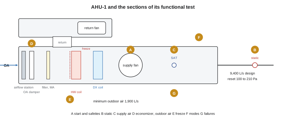
AHU-1 is a rooftop air handler serving all three floors through the 36 VAV boxes.
| Item | AHU-1 |
|---|---|
| Supply airflow (design) | 9,400 L/s (19,900 cfm); measured 9,750 L/s (20,650 cfm) at TAB |
| Fans | Supply and return fans on variable speed drives; return fan tracks the supply |
| Outdoor air | Economizer with outdoor, return and relief dampers; outdoor airflow station in the minimum outdoor air duct; design minimum 1,900 L/s (4,030 cfm) |
| Heating | Hot water coil served by the two condensing boilers |
| Cooling | Direct expansion cooling with four stages |
| Safeties | Freeze protection device across the heating coil face, high static pressure limit, duct smoke detectors (fire alarm system) |
| Key setpoints | Duct static reset 100 to 210 Pa (0.40 to 0.85 in. w.c.); supply air temperature reset 13 to 18 °C (55 to 64 °F); mixed air low limit 7 °C (45 °F) |
Before the test
Philippa's script began with prerequisites, and she checked each one before the first step.
- Pre-functional checklist complete, with the four No lines (lesson 3) closed.
- Point-to-point checkout accepted, including the return fan speed scaling corrected during checkout (lesson 4).
- TAB complete: airflow factors entered, static pressure maximum set from the balancer's measurement, outdoor airflow station corrected (lesson 7).
- Trends running on the 24 AHU-1 points at 1 minute, with a 10-second fast trend on supply air temperature, duct static pressure and the two fan speeds for the test days.
- Alarms routed to Ivo only.
- Halvern's operators told that AHU-1 would change modes during the day, and the tenants told that the third floor might be a little warm or cool for short periods.
The test was run with the building occupied, so the script avoided anything that would make spaces uncomfortable for long. The sections that needed the unit off (start-up and safeties) were done first thing on Monday before the tenants arrived, starting at 6:00.
| Section | Steps | What it tests |
|---|---|---|
| A. Start, stop and safeties | 8 | Start sequence, proofs, stop, high static limit, restart after power loss |
| B. Duct static pressure | 6 | Control at setpoint, response to a setpoint change, the reset between its limits |
| C. Supply air temperature | 8 | Heating and cooling control, staging, the reset |
| D. Economizer and minimum outdoor air | 8 | Economizer modulation, changeover to mechanical cooling, minimum outdoor air at reduced airflow, high limit |
| E. Freeze protection and low limit | 4 | Mixed air low limit; freeze protection trip and response |
| F. Modes | 5 | Unoccupied, warm-up, night low limit, occupied changeover |
| G. Failure responses | 3 | Supply air sensor failure, static sensor failure, loss of communication with the front end |
| Total | 42 |
Section A: start, stop and safeties
The start sequence is where mechanical damage happens if the controls are wrong: a fan started against closed dampers can over-pressurize the duct, and loops released too early wind up, as Callie had seen at Tilden in BAS-130. The sequence said: open the dampers to their start positions; when the outdoor damper's end switch proves it open, start the supply fan; when the supply fan's status proves it running, start the return fan; release the temperature and pressure loops 30 seconds after the supply fan is proven.
Worked problem
Checking the start timing
The outdoor damper actuator strokes fully in 95 s (from checkout). The supply fan is proven running 10 s after its start command, and the loops are released 30 s after proof. What is the earliest time after the start command that the loops can be released, and what did the trend need to show?
Show solution
- Dampers open and end switch proven: 95 s.
- Supply fan proven: 95 + 10 = 105 s.
- Loops released: 105 + 30 = 135 s.
Answer: About 135 s. The fast trend showed the damper command at 6:02:00, end switch at 6:03:36, supply fan status at 6:03:46 and the loops enabled at 6:04:16, 136 s after the command. Step A2 passed.
Step A5 tested the high static pressure limit. The script did not override anything: with Ivo at the front end and the mechanical contractor's technician at the unit, the static pressure setpoint was raised in small steps while a manometer at the limit switch was watched, until the hardwired limit tripped the supply fan at the switch's setting. The BAS showed the trip as an alarm and held the unit off until the switch was manually reset, as the sequence required. Step A8, restart after a power loss, was done by switching off the controller's power at its breaker for one minute and checking that the unit restarted through its full start sequence rather than jumping straight to running.
All eight steps in section A passed.
Section B: duct static pressure
With the unit running and the boxes in normal operation, step B1 checked that the static pressure held its setpoint (within 10 in 100 over a 10-minute period). Step B2 changed the setpoint and watched the response.
For step B2, Ivo lowered the setpoint from 210 to 150 Pa. The fast trend showed the fan slowing and the pressure settling within 10 Pa of the new setpoint in 70 seconds, with a small undershoot, and the criterion was settling within 2 minutes without sustained oscillation. B2 passed. Steps B3 and B4 tested the reset by putting the reset into its normal mode and watching it during the day: as boxes opened, the setpoint rose toward 210 Pa, and as they closed it fell.
Step B4 failed. At the end of Monday, as tenants left and boxes went to minimum, the reset reached its minimum of 100 Pa and the supply fan began to hunt: its speed swung about 8 Hz either side of its average with a period of about 40 seconds, and the static pressure swung with it. At low airflow the fan's effect on pressure is very different from at high airflow, and the loop gain that was fine at midday was too high in the evening. Sophie reduced the gain and lengthened the integral time slightly early on Tuesday morning, and on Tuesday evening the retest showed the pressure steady at 100 Pa. The issue was logged, fixed and closed, and the tuning values went into the sequence as built.
Ivo pointed out why the failure was found at all: the fast trend was running at 10 seconds, so a 40-second cycle had four samples per cycle on the 10-second trend and was obvious. On a 1-minute trend it would have looked like noise.
Section C: supply air temperature
Section C tested heating and cooling. Heating was easy in late October: the mornings were cold enough for the heating valve to modulate under real load, and steps C1 to C3 passed on the first try, with the supply air within its band.
Cooling needed planning. The afternoons were mild, about 12 to 14 °C (54 to 57 °F) on the test days, so the economizer could meet most of the load. To test the four cooling stages, the script lowered the supply air setpoint to its minimum and held the outdoor damper at minimum position, which forced mechanical cooling to run. Each stage was observed starting, with its minimum on and off times respected, as in BAS-220's compressor logic. Steps C4 to C8 passed, but at part load only. The script recorded that cooling at high outdoor temperature is deferred.
Section D: economizer and minimum outdoor air
The economizer steps checked that on a call for cooling with suitable outdoor air, the outdoor damper opened before any mechanical cooling ran, that the mixed air was controlled, and that mechanical cooling was added only when the economizer was fully open and could not meet the load. All passed on the mild Monday afternoon.
Step D5 tested something the old controls could not do: holding the minimum outdoor air at reduced supply airflow. With most boxes at minimum and the supply fan slowed, the airflow station reading was watched while the outdoor damper opened further to keep the flow at the design minimum.
Worked problem
Why the minimum outdoor air needs a measurement
At full design airflow, AHU-1 supplies 9,400 L/s with a minimum of 1,900 L/s outdoor air. In step D5 the supply airflow was about 5,600 L/s. What share of the supply is outdoor air at each airflow, if the minimum is held?
Show solution
- Full airflow: 1,900 ÷ 9,400 = 0.20.
- Reduced airflow: 1,900 ÷ 5,600 = 0.34.
Answer: The outdoor air fraction must rise from about 0.20 to about 0.34 as the supply airflow falls. A fixed damper position would have let the outdoor air fall with the fan. In step D5 the station read between 1,880 and 1,910 L/s with the damper further open, within the criterion of 5 in 100, and the step passed.
Step D7, the economizer high limit, could not be tested properly. It needs outdoor air warmer than the high limit, which does not happen in late October. Overriding the outdoor temperature would have tested the program's comparison but not the economizer's real behaviour on a hot, humid day. Philippa recorded D7 as deferred, together with cooling at high outdoor temperature, and logged it as one open item for June 2027 (a plan).
Section E: freeze protection
Section E was the most important for equipment protection, and it found the most interesting fault. Step E1 tested the mixed air low limit by lowering its setpoint until it acted, and passed. Step E2 tested the freeze protection device itself. The mechanical contractor's technician cooled the device's sensing element using the manufacturer's test method while everyone watched. The device tripped, the supply fan stopped through its hardwired circuit, the outdoor damper closed as the fan stopped, and the BAS showed the freeze alarm. The sequence also required the heating valve to open fully, to protect the coil while it was cold. It did not. It closed.
Ivo found the cause in a few minutes, and it was a lesson from BAS-130 coming back. After the integral windup problem at Tilden, Quillon's AHU template disables the temperature loops when the supply fan is off and sets their outputs to 0. On Marlow Lane, the freeze response had been written as a command to the valve, but the loop disable was later in the program and at a higher priority, so it won. The program was doing exactly what it said; two correct pieces of logic conflicted in one situation that only a test of the real device would show.
AHU-1 heating valve - output priority after the fix (generic logic)
IF freeze_trip THEN
    heating_valve := 100          (highest: coil protection)
ELSIF NOT supply_fan_proven THEN
    heating_valve := 0            (loop disabled with fan off)
ELSE
    heating_valve := heating_loop_output
END_IF
Freeze trip alarm stays until the device is manually reset AND an operator
acknowledges at the front end; unit then restarts through the full sequence.
Sophie made the change the same morning, and step E2 was repeated after lunch on Monday with the technician cooling the device again: fan stopped, damper closed, valve at 100, alarm shown, unit held off until the device was reset and an operator acknowledged. It passed. The issue was priority A and was closed the same day. The fix also went into Quillon's master AHU template, which is the step that stops the same conflict reaching the Tilden AHU-2 program next year.
Sections F and G: modes and failures
Section F tested the modes over a night. Ivo set AHU-1's schedule to end at 18:00 on Monday as normal, and the trend showed the unit stop, the boxes go to unoccupied mode, and, on Tuesday morning, the warm-up start at the time the optimal start chose, with the outdoor damper closed until occupancy. The night low limit was tested by raising its setpoint until the unit started in night heating, then restoring it. All five steps passed.
Section G tested failures. With Ivo at the front end, the supply air temperature sensor was disconnected at the controller: the sensor failure alarm appeared within a minute and the unit went to its failure response (heating and cooling held at safe positions, alarm to the on-call phone). The static pressure sensor was disconnected next: the fan went to a fixed safe speed and alarmed. Then the controller's network cable was unplugged: the front end showed AHU-1 offline within its timeout, and the unit kept running on its own program, as it should. All three passed, and every disconnected item was reconnected and checked before moving on.
The result
Worked problem
Summarizing the test
Of the 42 steps, 2 failed on the first attempt (B4 and E2) and passed on retest, and 1 (D7) was deferred. How many passed on the first attempt, and what share of the 42 is that?
Show solution
- Passed first time: 42 − 2 − 1 = 39.
- Share: 39 ÷ 42 = 0.929, about 93 in 100.
Answer: 39 of 42 passed first time, about 93 in 100; the two failures passed on retest, and one step is deferred to June 2027. Philippa signed the test as passed with one deferred step, and the three items went into the issues log: two closed, one open.
Ivo put the summary beside the earlier lessons. Neither failure would have been found by checkout: every point worked. The static pressure hunting showed only at evening loads, on a fast trend. The freeze response showed only when the real device was tripped. The deferred step was deferred because the season did not allow it, not because anyone ran out of time. And the fixes, retests and deferral were all in the issues log before the end of Tuesday, which is how the final report will be able to say exactly what was proven.
Planning the next one: Tilden AHU-2
Tilden Hall's AHU-2, the lecture wing unit, is planned for replacement in the summer of 2027, and Declan's proposal to Gus in early December is expected to include commissioning. Ivo suggested Callie start an outline of the AHU-2 functional test now, while Marlow Lane is fresh, using the same seven sections. Two things will be different. First, the season is reversed: a summer replacement can test cooling and the economizer high limit under real conditions, but heating and freeze protection under real load will have to be deferred to the winter of 2027 and 2028 (a plan). Second, AHU-2 serves lecture hall T-120 with demand-controlled ventilation, so the outline needs a section for the ventilation reset, tested with real occupancy during a lecture as well as with a test gas or a setpoint change.
Callie's outline will go to Ivo and then to whoever is appointed as Harcastle's commissioning provider, who will write the real script. Her job is to make sure the controls side of every section is ready: points that can be trended at 10 seconds, overrides available without touching safeties, and the freeze response tested with the real device, written into the template before anyone loads it.
Common mistakes
MistakeRunning an air handler test before the checklists, checkout and balancing are done.
InsteadCheck every prerequisite first; otherwise the test finds installation faults instead of sequence faults.
MistakeTesting safeties by overriding them in software.
InsteadOperate the real device with the right people present, as with the freeze protection device in step E2.
MistakeTesting loops only at the loads of the moment.
InsteadWatch them at low and high loads, with a fast trend, as step B4 showed.
MistakeOverriding the outdoor temperature to pass a seasonal step.
InsteadDefer the step to the right season and log it as open, as with step D7.
Summary and key terms
- A full air handler test runs through start and safeties, static pressure, supply temperature, economizer and outdoor air, freeze protection, modes and failures.
- Prerequisites (checklists, checkout, TAB, trends, notice to occupants) are checked before the first step.
- Fast trends during the test reveal behaviour such as loop hunting at low load.
- Testing the real freeze protection device revealed a conflict between two correct pieces of logic, fixed at the source.
- Results are recorded step by step; failures are retested, seasonal steps deferred, and every item logged.
- Start sequence
- The ordered steps an air handler follows when it starts: dampers, proofs, fans, then loops.
- End switch
- A switch on a damper or actuator that proves it has reached a position.
- Mixed air low limit
- A control function that limits the outdoor air when the mixed air becomes too cold.
- Failure response
- What a sequence does when a sensor, device or communication link fails.
- Output priority
- The order in which competing commands to one output are resolved.
Practice problems
Work each problem on paper first, then reveal the answer to check.
Why did the freeze trip close the heating valve instead of opening it?
Show answer
The loop disable logic (fan off, output 0) was later and at higher priority than the freeze response, so it won. The fix put the freeze response first.
Why was step D7 deferred instead of passed with an outdoor temperature override?
Show answer
An override would test only the program's comparison, not the economizer's real behaviour on a hot day; the step needs summer conditions.
At 5,600 L/s supply with 1,900 L/s minimum outdoor air, what is the outdoor air fraction?
Show answer
1,900 ÷ 5,600 = 0.34.
Lesson quiz · 5 questions
Score 60% or more to complete this lesson.
Create a free account to save your progress, take quizzes and earn a certificate.