
BAS-310 · Lesson 8 of 12 · 24 min
Modbus RTU and Modbus TCP
▶ Video coming soon A video version of this lesson is on the way.
The sixth network night, on Tuesday, November 3, followed a day at Ninefield looking at the lighting controls and the building's electrical submeters. That afternoon Callie had seen the main switchboard meter's readings on the front end and asked how they got there. That evening Prakash wired the bench power meter, the same model as Ninefield's, to a spare RS-485 port on the bench supervisory controller and handed her its manual, open at a twelve-page table of numbers. "BACnet devices describe themselves," he said. "Modbus devices hand you this and wish you luck."
A much older, much simpler protocol
Modbus was published by the controller maker Modicon in 1979 for its programmable logic controllers, and it became one of the most widely used protocols in industry because it was simple, openly published and free to use. It is now maintained by the Modbus Organization. In buildings it appears wherever industrial-style equipment does: electrical meters, variable frequency drives, generators, boilers, chillers, pumps and solar inverters. A building automation technician meets it on almost every large job.
Modbus is a request and response protocol between one client and one or more servers, traditionally called the master and the slaves. The client asks a server for some data or tells it to change something, and the server answers. Servers never speak unless asked. There is no discovery, no object model, no names and no units: a Modbus device is a set of numbered storage locations, and the only description of what each location means is the manufacturer's register map.
| Variant | Carried on | Notes |
|---|---|---|
| Modbus RTU | Serial lines, usually RS-485 | Compact binary frames with a CRC check; the common serial form in buildings |
| Modbus ASCII | Serial lines | Readable text frames; rarely seen in buildings now |
| Modbus TCP | Ethernet and IP, TCP port 502 | The same requests inside TCP, with a short header instead of the CRC |
The Modbus data model
Every Modbus device presents four tables of data. Coils and discrete inputs hold single bits; input registers and holding registers hold 16-bit words. The difference within each pair is whether the client may write: coils and holding registers can be written, discrete inputs and input registers are read-only.
| Table | Size of each item | Client may | Traditional reference numbers | Typical use |
|---|---|---|---|---|
| Coils | 1 bit | Read and write | 00001 to 09999 | Start and stop commands, enable bits |
| Discrete inputs | 1 bit | Read only | 10001 to 19999 | Status contacts, alarms |
| Input registers | 16 bits | Read only | 30001 to 39999 | Measurements in some devices |
| Holding registers | 16 bits | Read and write | 40001 to 49999 | Measurements, setpoints and settings in most devices |
The reference numbers in the fourth column are a convention from Modicon's manuals, not part of the protocol itself. The first digit names the table and the rest count from 1, so 40001 means the first holding register. On the wire, however, the request carries only the function code, which names the table, and an address counted from 0. Register 40001 is sent as holding-register address 0; register 43060 is sent as address 3059. Some manuals use six-digit references such as 403060, some list the 0-based address directly, and some list both. Getting this wrong by one is the most common Modbus integration error there is.
Worked problem
From a manual reference to the address on the wire
The bench meter's manual lists total real power as holding register 43060, a 32-bit floating-point value occupying two registers, and states that register numbers are 1-based. What function code and starting address should the client send, and how many registers should it read?
Show solution
- Table: 4xxxx means holding registers, read with function code 03.
- Address: 43060 − 40001 = 3059.
- In hexadecimal: 3059 = 11 × 256 + 15 × 16 + 3 = 0BF3.
- A 32-bit value spans two registers, so read 2 registers.
Answer: Function 03, starting address 3059 (0BF3 hexadecimal), quantity 2. Asking for address 3060 instead would read the second half of this value and the first half of the next one, and return a plausible-looking but wrong number.
Function codes
Each request starts with a function code saying what the client wants. A building technician rarely needs more than eight of them.
| Code | Function | Table |
|---|---|---|
| 01 | Read coils | Coils |
| 02 | Read discrete inputs | Discrete inputs |
| 03 | Read holding registers | Holding registers |
| 04 | Read input registers | Input registers |
| 05 | Write single coil | Coils |
| 06 | Write single register | Holding registers |
| 15 | Write multiple coils | Coils |
| 16 | Write multiple registers | Holding registers |
If a server cannot carry out a request, it answers with an exception: the function code with its top bit set, followed by an exception code. Exception 01 means the function is not supported, 02 an illegal data address, 03 an illegal data value and 04 a failure in the server. Exceptions 0A and 0B come from gateways and mean the gateway could not reach the device behind it. An exception 02 on a read that should work almost always means the address is off, or the read crosses into a range the device does not have.
Modbus RTU on RS-485
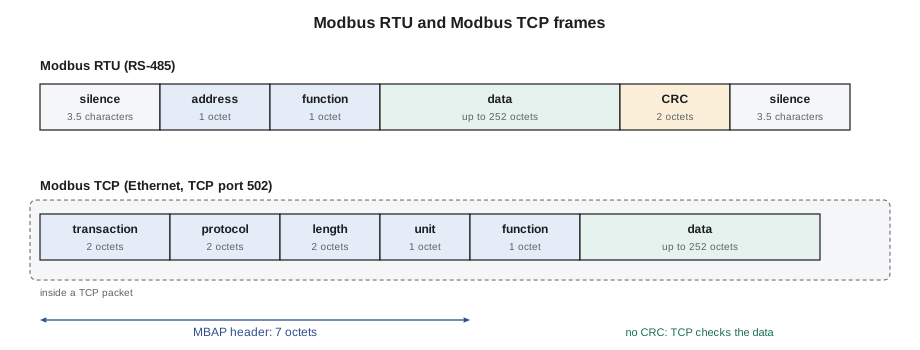
Modbus RTU runs on the same kind of EIA-485 trunk as MS/TP, daisy-chained and terminated at both ends, but it is a different protocol and the two must never share a trunk. Each server has an address from 1 to 247; address 0 is a broadcast that servers act on without answering. There is no token: the client simply asks one server at a time and waits for the answer, up to a timeout, before asking the next.
Every device on the trunk must use the same baud rate, data bits, parity and stop bits. The standard default is 19,200 bits per second, 8 data bits, even parity and 1 stop bit, often written 19200 8E1. Many devices ship set to 9,600 with no parity and 1 or 2 stop bits, so the settings must be checked on every device. Each character then takes 11 bit times: a start bit, 8 data bits, a parity bit and a stop bit. Frames are separated by a silence of at least 3.5 character times, which is how a device knows a new frame has begun, and each frame ends with a 16-bit CRC check.
Request  01 03 0B F3 00 02 cc cc
         01        server address 1
         03        function: read holding registers
         0B F3     starting address 3059
         00 02     quantity: 2 registers
         cc cc     CRC
Response 01 03 04 44 1B E0 00 cc cc
         04        byte count: 4
         44 1B     first register
         E0 00     second register
Worked problem
Time on the wire for one Modbus RTU read
At 19,200 bits per second with 8E1 framing, how long do the 8-octet request and 9-octet response above take on the wire? How many such reads per second could the trunk carry at most, if the meter takes about 20 ms to answer and the client waits 3.5 character times between frames?
Show solution
- Bits per character: 11. Request: 8 × 11 ÷ 19,200 = 4.6 ms. Response: 9 × 11 ÷ 19,200 = 5.2 ms.
- Silence between frames: 3.5 × 11 ÷ 19,200 = 2.0 ms, twice per exchange: 4.0 ms.
- One exchange: 4.6 + 20 + 5.2 + 4.0 = 33.8 ms, so at most about 1 ÷ 0.0338 = 29 reads per second.
Answer: About 30 reads a second at best. A gateway polling ten meters for twenty values each with single-register reads would take several seconds per cycle, which is why reading blocks of consecutive registers in one request matters.
Numbers larger than 16 bits
A Modbus register holds 16 bits, enough for an integer from 0 to 65,535, or −32,768 to 32,767 if it is signed. Most measurements need more range or decimals, and manufacturers handle this in several ways, all documented only in the register map. Some store a scaled integer: a voltage of 241.6 V stored as 2416 with a stated scale of 0.1. Some store a 32-bit integer across two registers, such as an energy total. Many modern meters store IEEE 754 32-bit floating-point numbers across two registers.
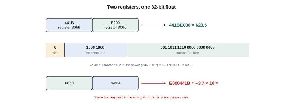
The protocol defines that each register is sent with its high byte first. It says nothing about which of two registers holds the high half of a 32-bit value. Most devices send the high word first, but a significant minority send the low word first, and some let the installer choose. Reading two registers in the wrong order turns a sensible value into nonsense, and the nonsense is not always obviously wrong.
Worked problem
Decoding a floating-point value and a 32-bit integer
The meter returns registers 441B and E000 (hexadecimal) for total power, high word first. (a) What value is that? (b) What would a client that assumes low word first display? (c) The energy total is an unsigned 32-bit integer in two registers, high word first, reading 12 and 34,567 in decimal. What is the energy in kilowatt-hours if the map gives a scale of 1 kWh?
Show solution
- (a) 441BE000: sign 0; exponent 88 hexadecimal = 136, minus the bias of 127 = 9, so the value is 1.fraction × 2⁹. Fraction bits 1BE000 hexadecimal give 1.21777 (to five places); 1.21777 × 512 = 623.5 kW.
- (b) Swapped, the pattern is E000441B: sign 1, a large exponent, decoding to about −3.7 × 10¹⁹ kW.
- (c) 12 × 65,536 + 34,567 = 786,432 + 34,567 = 820,999 kWh.
Answer: 623.5 kW and 820,999 kWh. The swapped reading is obviously wrong, but swapped integers, or a float read one register off, can produce values that look plausible, so every new Modbus point should be checked against the device's own display.
Modbus TCP
Modbus TCP carries the same function codes and data over Ethernet and IP. A client opens a TCP connection to port 502 on the server and sends requests with a 7-octet header, the MBAP header, in place of the RTU address and CRC: a transaction identifier to match answers to requests, a protocol identifier of 0, a length, and a unit identifier. TCP's own checks replace the CRC.
The unit identifier matters when the TCP server is a gateway to an RTU trunk. The gateway uses it as the RTU server address of the device behind it, so one gateway at one IP address can serve 30 meters on a trunk, each reached by a different unit identifier. When the TCP server is itself the device, the unit identifier is often ignored or must be 1 or 255; the device's manual says which.
Practical rules for Modbus integration
| Check | Why |
|---|---|
| Get the register map for the exact model and firmware | Maps change between versions |
| Confirm whether references are 0-based or 1-based | The most common error is an address off by one |
| Confirm data type, scaling, signed or unsigned, and word order | The map is the only description of what the bits mean |
| Match baud rate, parity and stop bits on every RTU device | One mismatched device corrupts the trunk |
| Read blocks of consecutive registers where possible | Fewer requests, faster polling; most devices allow up to 125 registers per read |
| Compare every new value with the device's own display | Plausible wrong values are worse than obvious ones |
| Write only the registers listed in the integration sheet | There is no priority array; a write simply replaces the value |
Callie set up the bench supervisory controller's Modbus driver with the meter at address 1, 19200 8E1, function 03, address 3059, two registers, float, high word first. The front end showed 0.0 kW, which was right for a meter with nothing connected to its current transformers. Prakash then plugged a heater into the bench circuit. The reading jumped to 1.4 kW, and the meter's own display agreed. "Now swap the word order," he said. She did, and watched the value turn into a string of digits with an exponent. "Remember that face," he said. "You'll see it again in August's job file."
Common mistakes
MistakeSending a manual's 1-based register number as the address.
InsteadSubtract 1 (and the table offset) when the map is 1-based, then verify.
MistakeAssuming every 32-bit value is high word first.
InsteadCheck the map, and test by comparing with the device display.
MistakePutting Modbus RTU and MS/TP devices on one trunk.
InsteadKeep each protocol on its own trunk.
MistakeLeaving one device at 9,600 with no parity on a 19200 8E1 trunk.
InsteadMatch baud rate, parity and stop bits on every device.
MistakePolling every register with its own request.
InsteadRead blocks of consecutive registers in one request.
Summary and key terms
- Modbus is a simple request and response protocol from 1979, used widely in meters, drives and plant equipment.
- Devices present coils, discrete inputs, input registers and holding registers; only coils and holding registers can be written.
- Reference numbers such as 40001 are 1-based conventions; the wire carries a function code and a 0-based address.
- Modbus RTU runs on RS-485 with addresses 1 to 247, matched serial settings and a CRC on each frame.
- Modbus TCP uses port 502 and a 7-octet header with a unit identifier, often used to reach devices behind a gateway.
- Values larger than 16 bits span two registers; scaling, sign and word order come only from the register map.
- Every new Modbus point should be checked against the device's own display.
- Modbus
- A request and response protocol first published by Modicon in 1979.
- Register
- A 16-bit storage location in a Modbus device.
- Holding register
- A 16-bit register that a client can read and write.
- Coil
- A single-bit value that a client can read and write.
- Function code
- The number in a Modbus request saying what operation is wanted.
- Register map
- The manufacturer's table describing each register's meaning, type and scaling.
- Word order
- Which of two registers holds the high half of a 32-bit value.
- Modbus RTU
- The binary serial form of Modbus, usually on RS-485.
- Modbus TCP
- Modbus carried over TCP/IP, by default on port 502.
- Unit identifier
- The field in a Modbus TCP header that selects a device, often one behind a gateway.
Practice problems
Work each problem on paper first, then reveal the answer to check.
A map lists voltage at 1-based holding register 43020. What address and function code are sent?
Show answer
Function 03, address 3019.
Registers 4396 and 8000 (hexadecimal), high word first, as a float?
Show answer
4396 8000 = 301.0.
A register reads 2416 with a scale of 0.1 V. What is the voltage?
Show answer
241.6 V.
How long does a 9-octet RTU frame take at 9,600 bits per second with 8N1 framing?
Show answer
8N1 is 10 bits per character: 9 × 10 ÷ 9,600 = 9.4 ms.
A gateway answers with exception 0B. What does that tell you?
Show answer
The gateway could not get a response from the device behind it.
Lesson quiz · 5 questions
Score 60% or more to complete this lesson.
Create a free account to save your progress, take quizzes and earn a certificate.