
BAS-310 · Lesson 12 of 12 · 21 min
Integrating a chiller and a meter: a case study
▶ Video coming soon A video version of this lesson is on the way.
After the November 3 network night, Prakash lent Callie a thick folder labelled NINEFIELD CH-1, CH-2, PM-1 INTEGRATION, AUG 2026. It recorded a job he and Sophie had done the month before Callie joined Quillon: connecting Ninefield Tower's two basement chillers and its main electrical meter to the building system. It was the job that had made possible the trends Callie and Prakash used on October 6 to find the plant's low delta-T, and it would supply most of the data for the chilled water retro-commissioning planned for spring 2027. "Read it as a checklist," he said. "Every mistake in it is one we caught. Most of them are in the earlier lessons."
The starting point
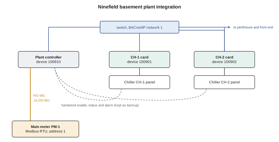
Until August 2026, the building system knew very little about Ninefield's chillers. Each of the two 700 kW water-cooled centrifugal chillers was wired to the basement plant controller with three hardwired points: an enable relay, a run status contact and a common alarm contact. The chillers' own control panels knew their leaving and entering water temperatures, their load, their power draw, their run hours and the reason for every alarm, but none of that reached the BAS. When a chiller tripped, the front end showed "CH-1 alarm" and someone had to go to the basement to read the panel.
The main switchboard meter, PM-1, was in the same position. It had been installed with a Modbus RTU port when the switchboard was renewed, but the port had never been connected. Ilona Vescovi read its display once a month for her own records. Her energy consultant had recommended trending both the chillers and the meter before any retro-commissioning, so that savings could be measured, and in July she approved Declan's quote for the integration.
Planning: the PICS, the map and the points list
On Monday, August 10, Prakash met Owen Kessock of Tarrant Chiller Service, the company that maintained Ninefield's chillers, in the plant room. Tarrant would supply and configure a BACnet/IP communication card for each chiller panel; Quillon would run the network cable, map the points and do everything on the BAS side. Before the meeting Prakash had read the card's PICS and its BTL listing: an application specific controller profile, with DS-RP-B, DS-RPM-B, DS-WP-B and DS-COV-B, supporting change-of-value subscriptions on its analog objects, and no segmentation.
The chiller card offered more than 300 objects. The integration points list, agreed that morning between Prakash, Owen and the energy consultant by phone, used 14 for each chiller.
| Point | Object | Direction | Update | Purpose |
|---|---|---|---|---|
| Chiller enable | BV | Write, priority 16 | On change | Plant staging from the BAS |
| Chilled water supply setpoint | AV | Write, priority 16 | On change | Chilled water reset from the BAS |
| Local or remote mode | MSV | Read | COV | Shows whether the panel will accept BAS commands |
| Running, alarm and alarm code | BV, BV, MSV | Read | COV | Status and the reason for trips |
| Leaving and entering chilled water temperature | AI, AI | Read | COV, 0.1 K increment | Delta-T and load |
| Entering and leaving condenser water temperature | AI, AI | Read | COV, 0.2 K increment | Tower performance |
| Load, 0 to 100 | AI | Read | 60 s | Staging and efficiency |
| Chiller power, kW | AI | Read | 60 s | Efficiency (kW per unit of cooling) |
| Run hours and starts | AI, AI | Read | 15 min | Lead-lag rotation and maintenance |
| Card heartbeat | AI | Read | 30 s | Detects a failed card or panel link |
The device instances came from Ninefield's plan in lesson 6: the basement plant controller was already 100910, and the chiller cards became 100901 and 100902. Ilona's IT contractor assigned two fixed IP addresses on the building controls network and confirmed that the chillers would sit on the same subnet as the plant controller, so no BBMD changes were needed.
Day 2: installing the cards
On Tuesday, August 11, Owen fitted the cards, one chiller at a time so that one was always available. Both cards came from the factory with the same default device instance, and Owen set them to 100901 and 100902 before connecting either to the network, the lesson 6 rule applied before it could cause trouble. He set the IP addresses, the UDP port to 47808 and the time synchronization source to the plant controller, and recorded every setting in Tarrant's service report, a copy of which went into the folder.
Owen also explained a feature of the chiller panels that the PICS could not: each panel had a local or remote switch in its software. In local mode the panel ignored every write from the network and ran on its own setpoint; only in remote mode would it accept the BAS's enable and setpoint. That was the reason for the mode point on the list. The integration sheet recorded that Tarrant's technicians would put a chiller in local mode during service and return it to remote mode afterwards, and the BAS would alarm if a chiller stayed in local mode for more than four hours.
Day 3: discovery, reading and the first write
On Wednesday, August 12, Sophie discovered the two cards from the front end with a Who-Is limited to 100900 to 100999 and read their object lists. She mapped the 28 points into the plant controller's database with Ninefield names, NF.CH1.CHWS-T and so on, set up change-of-value subscriptions for the temperatures and status points, and polled the rest at the rates on the list.
The first write failed. Sophie wrote a test setpoint of 7.0 °C to CH-1's setpoint object at priority 16 and the card answered with an error. CH-1's panel was still in local mode after the card installation. Once Owen switched it to remote, the same write succeeded and the panel's display showed the new setpoint within a few seconds. The second surprise was in the card's documentation: its setpoint object was a non-commandable Analog Value, with no priority array. A write at any priority simply replaced the value, as lesson 7 warned. The sheet was updated to say so, and the front end was configured so that only the plant program, not operators, could write it; operators who needed a different setpoint would change the program's reset limits instead.
Front end -> 100901  WriteProperty  analog-value,3  Present_Value 7.0  priority 16   invoke-id 41
100901 -> Front end  Error  error-class property  error-code write-access-denied      invoke-id 41
   (panel in LOCAL mode)
Front end -> 100901  WriteProperty  analog-value,3  Present_Value 7.0  priority 16   invoke-id 42
100901 -> Front end  SimpleACK                                                        invoke-id 42
   (panel switched to REMOTE)
Day 4: the meter
On Thursday, August 13, Prakash connected PM-1. The plant controller's spare RS-485 port ran a Modbus RTU client driver, and a new shielded pair ran about 25 m (80 ft) from the plant controller to the switchboard room, terminated at both ends. The meter shipped at 9,600 bits per second with no parity; Prakash set it to Quillon's standard of 19,200 with even parity and one stop bit, and server address 1. The integration list for PM-1 had twelve values: real power on each phase and in total, voltage and current on each phase, power factor, demand and the energy total.
Two mistakes from lesson 8 appeared in the first hour. The total power read about −3.7 × 10¹⁹ kW: the meter was set at the factory to send the low word of each float first, and the driver assumed high word first. Changing the driver's word order for that device fixed every float at once, and total power read 623.5 kW, matching the meter's display on a warm August afternoon. Then the energy total read a value that rose and fell from minute to minute. The map listed energy at 1-based register 43204, and Prakash had entered 3204 as the address instead of 3203, so the driver was reading half of the energy value and half of the next one. With the address corrected, the total read 820,999 kWh, again matching the display.
Worked problem
Checking the chiller data makes sense
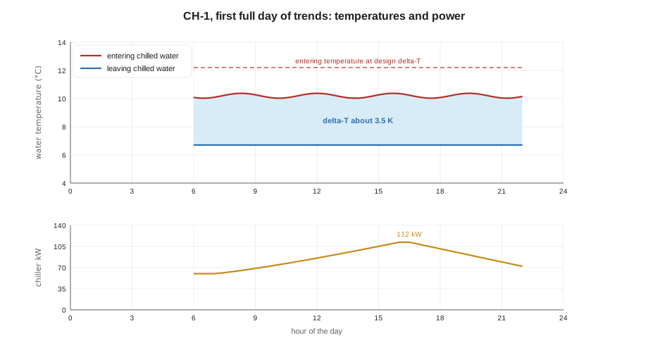
Late on August 14, CH-1 showed leaving chilled water at 6.7 °C, entering at 10.2 °C, a flow of 30 L/s taken from the balancing report rather than the plant's old insertion flow meter, which was later found to read low, and a power draw of 112 kW. What cooling was it producing, what was its efficiency as a coefficient of performance and in kW per ton, and how did the flow and delta-T compare with the design 30 L/s at 5.5 K?
Show solution
- Delta-T: 10.2 − 6.7 = 3.5 K.
- Cooling: 30 × 4.19 × 3.5 = 440 kW.
- Coefficient of performance: 440 ÷ 112 = 3.9.
- kW per ton: 440 kW ÷ 3.517 = 125 tons; 112 ÷ 125 = 0.90 kW per ton.
- At the design delta-T of 5.5 K, the same 30 L/s would carry 30 × 4.19 × 5.5 = 691 kW, the chiller's full rating.
Answer: About 440 kW of cooling at a COP of 3.9, or 0.90 kW per ton. The chiller was moving its full design flow but doing only about two thirds of the work it could, because the water came back only 3.5 K warmer instead of 5.5 K. That was the low delta-T Callie and Prakash confirmed on site on October 6, in BAS-110, visible in the data from the first week of the integration.
Day 5: testing end to end
On Friday, August 14, Prakash and Owen tested every point end to end, following the responsibility matrix in lesson 10. For each read value they compared the front end with the chiller panel or meter display; for each write they commanded the value from the BAS and watched the panel respond; for each alarm they asked Owen to simulate the condition, or used one the chiller could raise safely, and checked that the alarm arrived with the right code. They unplugged CH-2's card cable for two minutes and confirmed that the heartbeat alarm arrived and that every CH-2 value was flagged unreliable on the graphic, then plugged it back in.
They also kept the old hardwired enable, status and alarm wires. The plant program used the network values for staging and the hardwired ones as a backup: if the network status and the hardwired status disagreed for more than two minutes, or the card heartbeat failed, the program alarmed and fell back to the hardwired points. A network integration should add information, Prakash had written in the margin, not remove the last line of defence.
| Item | Planned | Actual |
|---|---|---|
| Chiller points mapped and tested | 28 | 28 |
| Meter values mapped and tested | 12 | 12 |
| Faults found during testing | — | 4: panel in local mode, non-commandable setpoint, meter word order, meter register off by one |
| Quillon hours | 32 | 38 |
| Trends started | Friday, August 14 | Friday, August 14, at 16:00 |
What the integration changed
By the end of August the folder held trends that nobody had been able to see before. The chillers' delta-T was low all day, every day. Both chillers often ran together at part load, a pattern Ilona had long suspected from the plant room. The main meter showed that the building's demand peaked at about 4 p.m. on hot days, when both chillers and every air handler ran together. When Callie and Prakash went to the plant on October 6, they arrived with those trends already in hand, which is why that visit took a morning and not a week.
The data now underpins the spring 2027 retro-commissioning. The valve conversions on the two oldest air handlers, the differential pressure reset on the secondary pumps and the chiller staging changes will each be judged against the August and September trends: the plant's delta-T, its kW per ton and the meter's demand peaks. Without the integration, the savings could only be estimated; with it, they can be measured.
Callie closed the folder at the last page, Prakash's handover note to Ilona. It listed the points, the passwords' location in Quillon's secure records, the local and remote mode rule, the hardwired backup, and one line underlined twice: "Before any chiller panel or card firmware is updated, Tarrant and Quillon agree the date, and Quillon backs up the plant controller and checks every mapped point afterwards."
Common mistakes
MistakeMapping hundreds of chiller objects because the card offers them.
InsteadAgree a short integration points list with the equipment supplier and engineer.
MistakeAssuming a chiller will accept network writes as soon as it is connected.
InsteadCheck the panel's local or remote mode and alarm if it stays in local.
MistakeTreating a setpoint object as commandable without checking.
InsteadCheck for a priority array, and control who may write it.
MistakeAccepting a meter value because it is a plausible number.
InsteadCompare every mapped value with the device's own display.
MistakeRemoving hardwired safeties once the network integration works.
InsteadKeep hardwired backups and fall back to them when the network fails.
Summary and key terms
- Integration began with the PICS, the BTL listing and an agreed points list of 14 points per chiller and 12 meter values.
- Device instances followed the site plan and were set before the cards joined the network.
- The chiller panels accepted writes only in remote mode, and the setpoint object had no priority array.
- The meter needed matching serial settings, the right word order and a corrected register address.
- Every point was tested end to end against the equipment, including alarms, heartbeat loss and fallback to hardwired points.
- The first week's data already showed the plant's low delta-T, found on site in October.
- Trends from the integration will measure the results of the spring 2027 retro-commissioning.
- Integration
- Connecting third-party equipment to the BAS so that agreed values can be read and written.
- Communication card
- An option board that gives equipment a network interface such as BACnet/IP.
- Local mode
- A panel setting in which equipment ignores network commands.
- Remote mode
- A panel setting in which equipment accepts network commands.
- End-to-end test
- Checking a value from the equipment all the way to the front end, or a command the other way.
- Hardwired backup
- Wired enable, status and alarm points kept alongside a network integration.
- kW per ton
- Electrical power per ton of cooling, a measure of chiller efficiency; lower is better.
- Coefficient of performance
- Cooling produced divided by electrical power used; higher is better.
Practice problems
Work each problem on paper first, then reveal the answer to check.
A chiller cools 30 L/s from 12.0 °C to 6.5 °C while drawing 120 kW. What is the cooling and the COP?
Show answer
30 × 4.19 × 5.5 = 691 kW; 691 ÷ 120 = 5.8.
The meter's total power reads 301.0 kW after the word order is fixed. What registers, high word first, does that come from?
Show answer
4396 and 8000 in hexadecimal.
A chiller write returns write-access-denied. What should be checked first?
Show answer
Whether the panel is in local mode, then whether the object is writable.
Why was the chiller setpoint restricted to the plant program?
Show answer
It has no priority array, so any writer would simply replace the value.
A chiller's network status says running but its hardwired status says stopped for five minutes. What should the program do?
Show answer
Alarm, and fall back to the hardwired points.
Lesson quiz · 5 questions
Score 60% or more to complete this lesson.
Create a free account to save your progress, take quizzes and earn a certificate.