
BAS-110 · Lesson 12 of 12 · 22 min
Walking a building: tracing systems from plant to zone
▶ Video coming soon A video version of this lesson is on the way.
On Thursday, November 12, a work order came in from Tilden Hall: room 108, a ground-floor classroom, had been too hot all week. The instructor said it was 27 degrees by mid-morning, students were opening the windows on a cold, grey November day, and the room's thermostat showed 26 °C against a setpoint of 22. Prakash looked at the request on his phone and handed it to Callie. "You've spent ten weeks learning the systems one at a time," he said. "Today you walk the whole building, from the steam main to that room, and tell me where the heat is coming from."
This lesson follows that walk. It shows how a controls technician traces a building's systems from the central plant through the distribution to the air handlers and the terminal units in a single room, and how each step uses the knowledge from lessons 1 to 11. It closes with a method for walking any building and a checklist for the first visit to a new site.
Before leaving the van
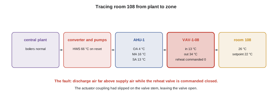
Callie started where Prakash always started: on the front end. She opened room 108's graphic and its trends for the past week. The room was served by VAV box VAV-1-08, a single-duct box with a hot water reheat coil, from AHU-1, and there was perimeter fin-tube radiation under its two windows. The trends showed that the room had been warm since the morning of Monday, November 9. Since then, the VAV box had been at its maximum cooling airflow whenever the room was occupied, the reheat valve command had been at zero, and the box's discharge air temperature, measured just downstream of the reheat coil, had been reading about 34 °C. Supply air from AHU-1, at the same time, was at its setpoint of 13 °C.
That one comparison already told her a lot. Air was leaving the air handler at 13 °C and leaving the box at 34 °C, while the controller was commanding no reheat at all. Something between the duct and the room was adding heat that the controls had not asked for. But Prakash asked her to walk the whole path anyway, partly to learn the building and partly because a technician who goes straight to the obvious answer sometimes misses a second problem.
Step 1: the plant and the converter
Callie's first stop was the basement mechanical room, where the steam main from the central plant entered the building. The steam pressure gauge upstream of the converter's control valve read normal for the season, and Nell's plant log, which she checked by phone, showed both boilers running normally. The converter's steam valve was modulating, about 40 in 100 open, and the hot water leaving the converter matched the reset schedule: 66 °C for the outdoor temperature that morning. One hot water pump was running, the other on standby, and the system pressure gauge was steady. The plant and the hot water loop were doing exactly what they should.
That ruled out one possibility Callie had considered: that the hot water supply was much too hot, which could make every coil with a leaking valve give off too much heat. If the whole loop had been too hot, many rooms would have complained, not one.
Step 2: the air handler
Next was AHU-1 in the fourth-floor fan room, which she knew from lesson 3. The outdoor air temperature was 4 °C. The mixed air temperature, 16 °C, gave an outdoor air fraction of (22 − 16) ÷ (22 − 4) = 0.33, close to the design minimum, as it should be in cool, damp weather when the economizer was holding mixed air for cooling. The preheat valve was closed, the cooling valve slightly open, and the supply air temperature at setpoint. The supply fan was at 72 in 100 of full speed, holding its duct static pressure setpoint. Nothing at the air handler explained a hot room.
She did notice one thing that was not related to room 108: the filter differential pressure on the final filters had risen to near its alarm limit. She noted it for the facilities staff. A good walk often turns up problems no one has reported yet.
Step 3: the duct and the box
Room 108 had a lay-in ceiling, so Callie set up a stepladder, put on gloves and moved a ceiling tile beside the VAV box. Before touching anything, she checked the box's controller on her laptop: airflow at its cooling maximum, damper about 80 in 100 open, reheat valve command 0. The supply duct upstream of the box felt cold through her glove. The discharge duct downstream felt hot. The reheat coil's hot water supply pipe was hot, and so was the return pipe, which meant water was flowing through the coil.
The reheat valve was a small two-way valve with an electronic actuator mounted on its stem. The actuator's position indicator showed closed, matching the controller's command. But when Callie, after asking Prakash, took the actuator's manual override and moved it a little, the indicator moved while the valve stem did not. The actuator's coupling to the valve stem had slipped. The actuator thought it was closing the valve; the valve had been left wide open.
This was the same kind of fault as the economizer actuators on Ninefield's rooftop units in lesson 4. The controller and the actuator agreed with each other and both were wrong about the device they were supposed to control. Without a discharge air temperature sensor downstream of the coil, the fault might have been invisible to the BAS except as a hot room.
Worked problem
How much heat was the stuck valve adding?
VAV-1-08 was delivering its maximum cooling airflow, which had been raised to 200 L/s (the design value is 150 L/s; see step 4). Air entered the box at 13 °C and left it at 34 °C, into a room held at 22 °C. How much heat was the box adding to the room, and how much cooling should it have been providing instead?
Show solution
- Heat added: 1.2 × 200 × (34 − 22) ÷ 1,000 = 2.88 kW.
- Cooling it should have provided: 1.2 × 200 × (22 − 13) ÷ 1,000 = 2.16 kW.
- Total swing: 1.2 × 200 × (34 − 13) ÷ 1,000 = 5.04 kW.
Answer: The box was adding about 2.9 kW instead of removing about 2.2 kW, a swing of about 5 kW. No wonder the room overheated, and the air handler and the converter were paying for both the cooling and the reheat.
Step 4: the room
In the room itself, Callie checked the other heat sources before declaring the case closed. The radiation valve under the windows was closed, as commanded, and the fin-tube was cool. The thermostat, mounted on an inside wall away from the windows and the projector, read within half a degree of her own calibrated thermometer. The windows were single-glazed like room 214's, but on a grey day they were not adding solar heat. The instructor's projector and the students added their own heat, which the box should have been able to remove. Everything else in the room agreed: the only unwanted heat was the air from the box.
She also noticed that the box's maximum cooling airflow had been raised from its design value of 150 L/s to 200 L/s on Wednesday, apparently by someone at the college trying to cool the room down from the front end. That had made the problem worse, because more air was passing through the open reheat coil. She noted it so that the value could be put back once the valve was fixed.
The repair and the follow-up
On Friday, November 13, Prakash and Callie returned with a new coupling and reset the actuator on the valve stem, then stroked the valve from fully closed to fully open from the laptop while Callie watched the stem move and the discharge air temperature follow. With the valve closed, the discharge air fell to within a degree of the supply air temperature within a few minutes. They restored the box's maximum airflow to its design value, released the override someone had set, and left a note in the work order explaining the fault and the fix. By the end of the afternoon, room 108 was at its setpoint.
Prakash suggested one more thing for the longer term, and Declan put it into the AHU-2 proposal that would go to Gus in early December: a fault detection rule for every VAV box with reheat and a discharge air temperature sensor, raising an alarm whenever the discharge air is more than a few degrees above the supply air while the reheat valve is commanded closed. The BAS already had all the data; it only needed the rule. BAS-330 covers fault detection and diagnostics.
A method for walking any building
Callie's walk followed a method that works in any building, from a small school to a hospital. Start with the complaint and the trends. Then follow the energy and the air from where they enter the building to where they are used, checking at each step whether conditions match what the design and the sequence expect. At each device, compare three things: what the controller commands, what the device reports, and what is physically happening. A fault lives where those three disagree.
| Step | What to look at | Questions to ask |
|---|---|---|
| Complaint and trends | Front end graphics, alarms, trend logs | When did it start? Which points changed? Is it one zone or many? |
| Central plant | Boilers, chillers, steam or water supply | Is the plant at setpoint and stable? Is anything in alarm? |
| Distribution | Pumps, converters, loops, pressures | Are supply temperatures and pressures right for the conditions? |
| Air handler | Dampers, filters, coils, fans, sensors | Do mixed and supply temperatures make sense? Is the fan holding pressure? |
| Terminal unit | VAV box, reheat, fan coil, radiation | Do command, feedback and physical condition agree? |
| Space | Thermostat, heat sources, envelope, occupants | Is the sensor right? What else adds or removes heat? |
Three habits make the method work. First, measure with your own calibrated instruments, not only the BAS sensors, because a failed sensor is a common cause of a complaint. Second, write down every reading as you go, with the time, so that you can compare readings at different points in the system and so that someone else can follow your work. Third, look for more than one cause: Callie found the slipped coupling, but also the raised maximum airflow that made it worse and the loaded filters at AHU-1 that would soon cause a different problem.
The first visit to a new building
When a controls technician visits a building for the first time, a structured walk is the fastest way to learn it. Get the drawings, the sequence of operations and a list of equipment. Find out who operates the building and how to reach them. Walk the plants, the air handlers, a sample of terminal units and the main electrical room. On the front end, look at the alarm list, the schedules, the overrides in effect and the trends that are being kept. Note which systems are on the BAS and which are not. Mark up the drawings with what you find. Prakash's version of this checklist fitted on one side of an index card, and he gave Callie a copy at the end of her first ten weeks.
- Who runs this building, and how do I reach them after hours?
- Where are the plants, air handlers, electrical rooms and lockout stations?
- What does the front end show: alarms, schedules, overrides, trends?
- Which systems are on the BAS, which are separate, and where are the boundaries?
- Do the drawings, schedules and sequences match what is installed?
- What has changed since the building was built, and what is not on any drawing?
Recording what you found
The last step of any walk is the record. Callie's service report for room 108 listed each reading she took, with the time and the instrument, the fault she found, the repair, the settings she restored and the recommendations for the future. It also listed the two unrelated findings: the loaded final filters at AHU-1 and the overridden maximum airflow. Prakash read it in the van and changed only one line, adding the part number of the coupling so that the next technician could carry a spare. A good report lets the owner see what was paid for, lets the next technician start where you finished and, over time, shows which faults keep coming back. Harcastle's work order system kept every report, and Gus Thibodeaux used them each spring to decide which equipment to replace.
Reports should be factual and plain. They describe what was found, not who was to blame, and they separate what was fixed from what is only recommended.
Common mistakes
MistakeGoing straight to the obvious device without looking at the rest of the system.
InsteadWalk the path; a second problem is often hiding upstream or downstream.
MistakeTrusting an actuator's position feedback as proof the valve or damper moved.
InsteadWatch the stem or blades move, or confirm with a temperature or flow change.
MistakeRaising airflow or lowering setpoints to cover a fault.
InsteadFind the fault, fix it, and put the settings back to design.
MistakeRelying only on BAS sensors.
InsteadCheck key readings with your own calibrated instruments.
MistakeNot writing readings down.
InsteadRecord each reading with the time and location so the work can be followed.
MistakeLeaving overrides and changed settings after a repair.
InsteadRelease overrides, restore settings and record what was done.
Summary and key terms
- A complaint is traced from the front end and trends to the plant, the distribution, the air handler, the terminal unit and the space.
- At each device, compare the command, the feedback and what is physically happening.
- Discharge air temperature far above supply air with reheat commanded closed means the reheat is open.
- Actuator feedback can be wrong if the coupling or linkage has slipped.
- Settings changed to cover a fault often make it worse and must be restored.
- Measure with calibrated instruments, record readings and look for more than one cause.
- Fault detection rules can catch stuck valves and dampers automatically.
- A structured first walk is the fastest way to learn a new building.
- Discharge air temperature
- The temperature of air leaving a terminal unit, after any reheat.
- Coupling
- The part that connects an actuator to a valve stem or damper shaft.
- Feedback
- A signal reporting a device's actual position or state back to the controller.
- Override
- A manual command that takes a point out of automatic control.
- Fault detection and diagnostics (FDD)
- Rules or software that detect equipment faults from BAS data.
- Field verification
- Checking drawings and data against what is physically installed.
- Calibrated instrument
- A meter checked against a known standard so its readings can be trusted.
- Work order
- A request for service that records the problem, the work done and the result.
Practice problems
Work each problem on paper first, then reveal the answer to check.
A box's discharge air is far warmer than its supply air, and its reheat valve is commanded closed. What is likely?
Show answer
The reheat valve is open or leaking, for example because its actuator coupling has slipped.
Why walk the whole path instead of going straight to the room?
Show answer
To confirm the rest of the system is right and to find other problems.
What three things should agree at every device?
Show answer
The controller's command, the device's feedback and what is physically happening.
Why should a raised airflow or setpoint be put back after a repair?
Show answer
It was a workaround that wastes energy or causes other problems once the fault is fixed.
Name three things to check on the front end on a first visit.
Show answer
Alarms, schedules and overrides in effect; also the trends being kept.
Lesson quiz · 5 questions
Score 60% or more to complete this lesson.
Create a free account to save your progress, take quizzes and earn a certificate.