
ARCH-420 · Lesson 8 of 12 · 21 min
BIM for documentation
Professor Lucía Ferreira, who taught the four students digital design in their second year, returns in the eighth week with a confession. Early in her career as a BIM manager she watched a project team spend three weeks drafting by hand a set of details that their model could have produced in three days, and then watched another team spend three days producing details from a model that were wrong in ways no one noticed, because the model looked complete. Building information modelling, she tells the students, does not make documentation easy. It moves the work. Less time goes into drawing lines and keeping drawings consistent; more goes into setting up the model properly, deciding what it should contain and checking that what it produces is right. This lesson is about using the model to produce construction documents, and about what it cannot do.
One model, many drawings
In a model-based workflow, the building is modelled once as a set of elements, such as walls, floors, roofs, doors, windows, beams and columns, each with geometry and properties. Drawings are views of that model. A floor plan is a horizontal cut through the model at a set height, with display rules that decide which elements appear and how; a section is a vertical cut; an elevation is a view from outside; a schedule is a table of the properties of a category of elements. When a wall moves, every plan, section, elevation and schedule that shows it moves with it. That is the single greatest benefit of modelling for documentation: the drawings can no longer disagree with one another about the geometry of the building.
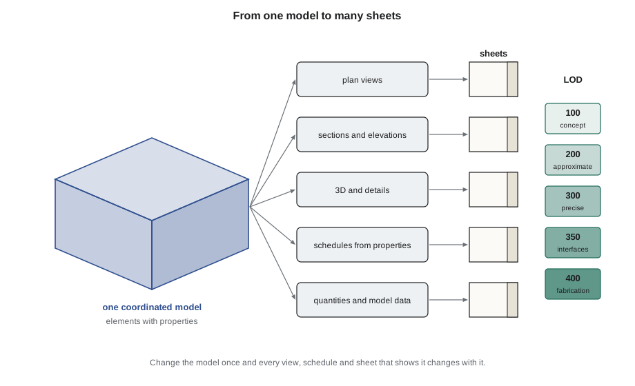
Views are placed on sheets, and the sheets carry the title block, the sheet number and the references. Most modelling software manages the references automatically: a section mark on a plan knows which view it cuts and which sheet that view is placed on, and updates when the view is moved. Sheet indexes, revision schedules and transmittals can all be generated from the sheet data. Brandt points out that this makes the conventions from Lesson 2 more important, not less. The software will happily number sheets A1, A-1 and A-001 in the same set if the team lets it; the office template must enforce the standard.
Annotation, meaning the dimensions, tags, notes and keynotes, lives in the views, not in the model, but it should still be tied to the model wherever possible. A door tag reads its mark from the door element, so the plan and the schedule always agree. A wall tag reads the wall type. A dimension attached to a wall moves with it. Text typed by hand is not tied to anything and will not update; a note that says 'gypsum board on steel studs' beside a wall that has since been changed to a mass timber panel will stay wrong until a person notices.
What the model should contain
A model can contain too little or too much. If the walls are generic, with no layers, the wall sections cannot be cut from them and must be drawn by hand. If every screw is modelled, the model becomes slow, and no one will maintain it. The team must decide, element by element and phase by phase, how much geometry and information each element needs. The Level of Development specification published by BIMForum gives a common vocabulary: an element at level 100 is a concept, such as a mass; at 200 it has approximate size, shape and location; at 300 its size, shape, location and orientation are precise enough to be measured from the model; at 350 its interfaces with neighbouring elements are modelled; and at 400 it is detailed enough for fabrication. The construction documents of most buildings are produced at about 300, with some elements at 350.
The decisions are recorded in a BIM execution plan, agreed among the disciplines at the start of the project. On the Rail Yard Commons the plan sets the walls, floors, roof assemblies, doors, windows and structural members at 300, the glulam connections and the roof-tooth glazing at 350 because they meet so many other elements, and the furniture at 200. It names a model manager for each discipline, the file naming and folder structure, the shared coordinates, the frequency of model exchange and the checks each model must pass before it is shared. It also follows the information management principles of ISO 19650, the international standard that organizes project information in a common data environment through which each container passes from work in progress, to shared, to published and finally to archived.
Details are a special case. The large-scale details of the roof valleys, window heads and base of the wall can be cut from the model if the model is detailed enough, but very few teams model every flashing, sealant joint and fastener. The usual approach is a hybrid: the detail view is cut from the model to give the correct underlying geometry, and the small parts are drawn over it in 2D using detail components that carry their own properties. This is efficient and safe as long as the drafted parts are checked whenever the underlying geometry changes. Ferreira's three-day disaster came from exactly that: the model had been changed after the details were drafted, and the 2D flashings no longer met the walls they were drawn on.
Schedules and quantities
Because every element carries its properties, the model can produce schedules and quantities directly. Door and window schedules, room finish schedules and wall type tables are the obvious examples. Quantities are another: wall areas by type, floor areas by finish, lengths of glulam by size, numbers of each window type. These are useful for checking the design against the budget, for the specification, and for the cost consultant, who can use them as a starting point for an estimate. Joon-ho exports the wall data from the east wing model and computes the net areas by type.
# Net wall areas by type from a model export: gross area minus openings.
walls = [  # wall id, type, length m, height m, openings (width m, height m)
    ("W1", "EXT-1 panel wall", 24.0, 5.0, [(2.4, 2.8)] * 3),
    ("W2", "EXT-1 panel wall", 18.0, 5.0, [(1.8, 2.8)] * 2),
    ("W3", "EXT-2 brick base", 25.2, 1.2, []),
    ("W4", "INT-3 rated stair wall", 6.0, 9.8, [(0.915, 2.135)] * 2),
    ("W5", "INT-1 partition", 32.0, 3.0, [(0.915, 2.135)] * 6),
]
totals = {}
for wid, wtype, length, height, openings in walls:
    gross = length * height
    holes = sum(w * h for w, h in openings)
    t = totals.setdefault(wtype, [0.0, 0.0])
    t[0] += gross; t[1] += gross - holes
print(f"{'wall type':<24}{'gross m2':>10}{'net m2':>10}")
for wtype, (g, n) in sorted(totals.items()):
    print(f"{wtype:<24}{g:>10.1f}{n:>10.1f}")
# Gypsum board both faces of the partitions, with 10 for each 100 added for waste.
board = totals["INT-1 partition"][1] * 2 * 1.10
print(f"gypsum board for INT-1 (both faces, with waste): {board:.0f} m2")wall type gross m2 net m2 EXT-1 panel wall 210.0 179.8 EXT-2 brick base 30.2 30.2 INT-1 partition 96.0 84.3 INT-3 rated stair wall 58.8 54.9 gypsum board for INT-1 (both faces, with waste): 185 m2
Brandt is careful about what such numbers are for. Quantities from the design model help the team, but they are not part of the contract under CCDC 2, and bidders must do their own take-offs from the contract documents. If the team wants to share the model with bidders, it should do so under an agreed protocol that states the model's purpose and level of development and makes clear that the drawings and specifications govern. Some Canadian owners now attach a BIM protocol or schedule to the contract that sets out who may rely on the model and for what.
Coordination in the model
When each discipline models its own work in shared coordinates, the models can be combined, or federated, and checked against one another. Clash detection software finds elements that occupy the same space, such as the duct and the glulam beam at grid E from Lesson 7, and elements that come closer than a set clearance, such as a pipe within 50 mm (2 in) of a sprinkler head. Clashes are grouped, assigned and tracked through issue reports, often in the open BCF format, which lets the issues travel between software packages. The open IFC format lets models from different software be combined at all. Ferreira reminds the students that clash detection finds what was modelled. A duct that the mechanical engineer has not yet modelled cannot clash with anything, and a federated model with no clashes may simply be an incomplete one.
The team also uses the model to check the documents themselves. Joon-ho sets up rules that flag doors with no mark or no rating property, walls of a rated type that do not reach the structure above, rooms with no number and sheets with views that are not referenced from anywhere. These model checks are the automated part of the quality control process that Lesson 9 describes. They do not replace a person reading the set, but they clear away the mechanical errors so that the reader can concentrate on the ones that need judgment.
From model to issued set
When the set is issued, it is published from the model as PDF sheets, often with a digital signature or seal applied by the responsible professional, and the published set, not the model, becomes the document of record for that issue. The model continues to change; the issued set must not. Every issue therefore needs a frozen copy of the sheets and, in many offices, an archived copy of the model as it stood, so that the team can later show exactly what was issued and why. Revisions are clouded and logged in the model's revision table, so that the sheets carry their revision history automatically.
At the end of construction the model can be updated to reflect what was built and handed to the owner with the record drawings. For the city's facilities department, which will run the Rail Yard Commons for fifty years, a model whose doors, equipment and spaces carry the right properties can feed its maintenance system directly. That is a long way from the construction documents, but it starts with decisions made now: which properties each element carries, how they are named and who keeps them right.
Worked problem
Deciding what to model and what to draft
For the roof valley detail on A-501, decide which parts should be modelled at level 300 or 350 and which should be drafted over the cut, and explain how the team will keep them consistent.
Show solution
- Model at 300: the glulam beam, the CLT panel, the insulation layers, the metal roofing as a layered roof assembly, and the glazed unit at the base of the next tooth.
- Model at 350: the gutter and the sill of the glazing, because they meet the roof, the glazing and the structure and are checked for clashes.
- Draft over the cut: the membrane laps, the flashings, sealant joints, fasteners and the cricket's tapered pieces, using detail components with properties.
- Keep consistent: lock the detail view's cut location, add the detail to the checklist of views reviewed when the roof assembly changes, and note in the BIM execution plan who owns it.
Answer: Model what defines the geometry and the interfaces; draft the small parts; check the drafted parts whenever the model changes.
Exercise 8: setting up the east wing model for documentation
- Write the part of a BIM execution plan that sets the level of development for each element of the east wing.
- Set up the door and wall tags so that they read their values from the model, and replace any text typed by hand.
- Export the quantities of each wall and floor type and compare them with the elemental cost plan from Design Studio VI.
- Write five model checks that flag missing or inconsistent properties before each issue.
Self-check
- Does every tag and schedule read its values from the model?
- Have I recorded the level of development for each element and who owns it?
- Are the drafted parts of my details checked when the model changes?
- Is each issued set frozen and archived separately from the working model?
Common mistakes
MistakeAssuming a model that looks complete is correct.
InsteadCheck properties and drafted details as carefully as hand-drawn sheets.
MistakeTyping notes and tags by hand in a model.
InsteadTie annotation to the elements so it updates with them.
MistakeModelling everything to fabrication detail.
InsteadSet the level of development by element and draft the small parts over the cut.
MistakeSharing the model with bidders without a protocol.
InsteadState its purpose and reliability, and make clear that the contract documents govern.
MistakeTreating a clash-free federated model as coordinated.
InsteadCheck that every discipline has modelled its elements before trusting the result.
Summary and key terms
- Drawings are views of a single model, so geometry can no longer disagree between drawings.
- Annotation should read from the model wherever possible; typed text does not update.
- A BIM execution plan sets the level of development, ownership, exchanges and checks for each element.
- Details are usually cut from the model and completed in 2D, which must be rechecked when the model changes.
- The published, frozen set, not the model, is the document of record for each issue unless the contract says otherwise.
- View
- A representation of the model, such as a plan, section or schedule, defined by a cut and display rules.
- Level of development
- The degree to which an element's geometry and information can be relied on, from 100 to 400.
- BIM execution plan
- The agreement among the disciplines on how the project's models are produced, shared and checked.
- Federated model
- A combination of discipline models in shared coordinates, used for coordination.
- Common data environment
- The managed repository through which project information passes from work in progress to published and archived.
Practice problems
Work each problem on paper first, then reveal the answer to check.
What is the main benefit of producing drawings as views of one model?
Show answer
The drawings cannot disagree with one another about the geometry of the building.
At what level of development are most construction documents produced?
Show answer
About 300, with some elements at 350.
Why might a federated model show no clashes and still be uncoordinated?
Show answer
Some disciplines may not have modelled their elements yet.
Can bidders rely on quantities taken from the design model?
Show answer
Not unless the contract says so; they must take off from the contract documents.
Why must each issued set be frozen?
Show answer
The model keeps changing, and the team must be able to show exactly what was issued.
Lesson quiz · 5 questions
Score 60% or more to complete this lesson.
Create a free account to save your progress, take quizzes and earn a certificate.