
ARCH-420 · Lesson 7 of 12 · 21 min
Coordination between disciplines
In the seventh week the studio fills with engineers. Marta Szymańska, the structural engineer who has followed the four students since their first structures course, brings the framing plans of the east wing. Kofi Mensah brings the mechanical layouts, and a new guest, Leah Kowal, an electrical engineer who has designed the power and lighting for a dozen public buildings, brings the electrical plans. Brandt lays the three sets on the table beside the students' architectural drawings and asks a simple question: where does the main supply duct cross the glulam beam line at grid E? Ten minutes later the room has found four answers, one on each set of drawings, and none of them agrees. That, Brandt says, is coordination, and it is where most of the cost of bad documents comes from.
Who draws what
A building of any size is documented by a team: the consultant and the structural, mechanical, electrical, civil and landscape engineers, often with specialists for code, acoustics, envelope, kitchens, audiovisual systems and many more. Each discipline is responsible for its own documents and for the design they describe. The consultant is usually the prime, holding the contract with the owner and the subcontracts with the engineers, and is responsible for coordinating the whole set. That does not make the consultant responsible for the engineering, but it does make them responsible for the places where the disciplines meet.
Coordination starts with a clear division of responsibility. At the start of the documentation phase the team should agree who shows what: who draws the floor slabs and their edges, who dimensions the openings in the CLT for ducts and pipes, who shows the housekeeping pads under the mechanical equipment, who specifies the motorized dampers and who wires them, who shows the backing in the walls for grab bars and wall-hung fixtures. These agreements are recorded in a responsibility matrix, a table listing items down one side and disciplines across the top, with one tick per item. Items that appear in no one's column are scope gaps, and they become extras. Items in two columns are overlaps, and they get priced twice or argued about.
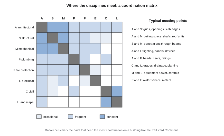
Some items are notoriously prone to falling between the disciplines. Lintels over masonry openings can be shown by the consultant or the structural engineer. Roof hatches, ladders and fall-protection anchors touch architecture, structure and often mechanical access. Power to door operators, hand dryers and the makerspace's dust collector sits between the architectural or mechanical specification and the electrical one. Fire stopping at penetrations involves every discipline that penetrates a rated assembly. Brandt asks the students to list ten such items for the east wing and assign each one before they draw another line.
The ceiling space
The single most common coordination problem is the space above the ceiling, where structure, ducts, pipes, sprinklers, cable trays, lights and the ceiling itself all compete for the same few hundred millimetres. In the east wing the problem is concentrated in the corridor along the upper floor of the east core, where the main supply and return ducts run between the glulam beam lines, and in the makerspace, where the roof teeth leave almost no ceiling space at all and the ducts must run exposed.
Mensah shows the students how engineers resolve this before drawing anything: by stacking up the zones. Starting from the underside of the structure, they add the depth of the deepest beam, the clearance needed below it, the depth of the largest duct with its insulation and hangers, a zone for sprinkler mains, a zone for lights and the ceiling system, and compare the total with the height available between the floor and the underside of the structure. If it does not fit, something has to change: the beam is made shallower or penetrated, the duct is flattened or rerouted, the ceiling is lowered, or the floor-to-floor height grows. Every one of those changes touches another discipline's drawings.
# Stack up the ceiling zone in the upper corridor of the east core.
floor_to_floor = 4800        # mm, upper floor to roof
roof_build_up = 245 + 75     # CLT panel and topping above the beam's top
beam = 646                   # glulam beam depth, mm
zones = [  # name, depth mm, can it pass between beams?
    ("duct (main supply) with insulation and hangers", 400, True),
    ("sprinkler main and branch lines", 100, True),
    ("cable tray", 100, True),
    ("lights and ceiling system", 150, False),
]
ceiling_target = 3000        # finished ceiling height wanted in the corridor, mm
underside_structure = floor_to_floor - roof_build_up
print(f"underside of panel above floor: {underside_structure} mm")
print(f"underside of beam above floor:  {underside_structure - beam} mm")
below_beam = sum(d for n, d, between in zones if not between)
between = sum(d for n, d, b in zones if b)
fits_between = between <= beam
ceiling = underside_structure - beam - below_beam if fits_between else underside_structure - between - below_beam
print(f"services that must fit between beams: {between} mm in a {beam} mm beam depth -> {'fits' if fits_between else 'does not fit'}")
print(f"highest ceiling possible: {ceiling} mm (target {ceiling_target})")
print("OK" if ceiling >= ceiling_target else f"short by {ceiling_target - ceiling} mm")underside of panel above floor: 4480 mm underside of beam above floor: 3834 mm services that must fit between beams: 600 mm in a 646 mm beam depth -> fits highest ceiling possible: 3684 mm (target 3000) OK
The stack-up shows that the services fit between the beams only if they run parallel to them; the ceiling can then sit just below the beams at a comfortable height. The catch, which Szymańska points out at once, is that the main supply duct has to cross a beam line once to reach the east end. The three options are a penetration through the beam, which she will allow only within a limited zone near mid-depth and away from the supports, with the hole sized and reinforced by her; a drop in the ceiling for one bay; or rerouting the duct through the shaft one bay earlier. The team chooses the shaft. The decision is recorded in the coordination log, and it changes the mechanical plans, the architectural reflected ceiling plan and the shaft dimensions on the enlarged core plan.
Overlays and coordination meetings
Coordination happens in two ways: by comparing documents and by talking. Before building information models, comparing meant overlaying: printing each discipline's plan of the same floor on translucent paper, laying them on a light table and looking for conflicts. The modern equivalent is federating the discipline models and running a clash detection, which Lesson 8 describes. Both methods find hard conflicts, such as a duct passing through a beam. Neither finds soft conflicts as well as an experienced eye: a diffuser that will blow across a reading desk, a light fixture centred on a ceiling grid that no longer exists, a panel board placed where a door will swing over it.
Coordination meetings, usually every one or two weeks during documentation, are where conflicts are resolved and recorded. Brandt sets three rules for the student team's meetings. Each issue has an owner and a date. Each decision is recorded in a log that every discipline can see, with the sheets it affects. And a decision is not closed until every affected sheet has been revised, a habit that the quality control process of Lesson 9 will check. The coordination log becomes one of the most useful documents of the project; months later, when a contractor asks why the duct runs through the shaft, the answer is in the log with its date.
Words as well as lines
The specifications need coordinating too. Every discipline writes its own sections, and they meet in Division 01 and at the boundaries between divisions. The classic examples involve controls and power. The mechanical sections specify the fans, dampers and controls; the electrical sections specify the power wiring; someone must specify the control wiring, the starters and the disconnects, and say who installs and connects each one. Many teams solve this with a responsibility table in the mechanical or electrical sections. Door hardware is another boundary: the door hardware section in Division 08 specifies electrified locks and power operators, while Division 26 provides the power and Division 28 the access control; the hardware supplier, the electrician and the security contractor must all read the same matrix.
Under CCDC 2 the contractor is responsible for coordinating the work of the trades and for reviewing shop drawings before submitting them, but that does not relieve the consultant of coordinating the design. If the drawings show a duct through a beam, the contractor who builds it as drawn and then discovers the conflict is entitled to be paid for the fix. Good coordination during documentation is cheaper than any change order during construction, and Brandt quotes a rule of thumb many in the industry use: a problem found on paper costs one, found during construction costs ten and found after occupancy costs a hundred.
Kowal adds a point from the electrical side. Architects often treat the electrical drawings as something that arrives at the end, but electrical rooms, panel locations, the main service, the generator connection the comprehensive studio added for the refuge room and the photovoltaic inverters all need space, ventilation and access that the architectural plans must provide. She asks the students to put every electrical room and every panel on their plans now, with the clearances in front of them, and to show the conduit route from the roof array to the inverters. Two of the panels turn out to be on walls that Callum had planned to glaze.
Worked problem
Closing a scope gap at the roof teeth
The makerspace roof teeth need motorized vents at the top of each glazed face for natural ventilation. The architectural drawings show the vents, the mechanical drawings show nothing, and the electrical drawings show no power. Decide how the item should be assigned and documented.
Show solution
- Identify the parts: the vent units (part of the glazing system), the actuators, the control sequence, the control wiring and the power.
- Assign the vent units and actuators to the glazing section in Division 08, specified to accept a control signal.
- Assign the control sequence and control wiring to the mechanical controls section in Division 25 or 23, so that the vents work with the HVAC system and the rain sensor.
- Assign the power supply to the actuators to Division 26, with a circuit shown on the electrical plans.
- Record the split in the responsibility matrix, add references between the three sections, and log the decision with the sheets affected.
Answer: Each part is assigned to one discipline, the sections refer to each other and the decision is logged.
Exercise 7: a coordination session
- Prepare a responsibility matrix for twenty items in the east wing that touch more than one discipline.
- Stack up the ceiling zones in the upper corridor and in the multipurpose room, and identify any conflicts.
- Overlay the architectural, structural and mechanical plans of the upper floor and list every hard and soft conflict you find.
- Run a coordination meeting with the engineers and record each decision with its owner, date and affected sheets.
Self-check
- Is every item that touches two disciplines assigned to exactly one of them?
- Have I stacked the zones where services and structure compete for space?
- Is every coordination decision logged with the sheets it changes?
- Do the specification sections at each boundary refer to one another?
Owner-supplied items and the existing site
Two more kinds of coordination are easy to forget. The first is the owner's own suppliers. On the Rail Yard Commons the city will buy the library shelving, the makerspace tools, the audiovisual equipment and the furniture under separate contracts, and some of it will be installed by the contractor. Each item needs space, structure, power, data and sometimes ventilation, and each needs a clear statement in the documents of who supplies it, who installs it and who connects it. Many offices use a short code in the schedules, such as supplied by owner and installed by contractor, defined in Division 01, so that every reader understands the split the same way.
The second is the site itself. The rail-yard parcel has buried fill with ash and cinders, a stormwater park on one side and a city street with utilities on the other. The civil and landscape drawings set the grades, the drainage and the utility connections, and the architectural drawings must agree with them at every door threshold, every ramp and every point where the building meets the ground. A floor level that differs by 50 mm (2 in) between the architectural and civil drawings will produce either a step at the entrance or water flowing toward the building. Brandt asks the team to list every point where the building touches the site and confirm each elevation on both sets of drawings.
Common mistakes
MistakeAssuming the engineers will coordinate with the architectural drawings.
InsteadLead coordination as the prime consultant and check the places where the disciplines meet.
MistakeLeaving items unassigned between disciplines.
InsteadUse a responsibility matrix so every item has one owner.
MistakeFinding the ceiling conflicts during construction.
InsteadStack up the zones and resolve conflicts on paper during documentation.
MistakeRelying on clash detection alone.
InsteadLook for soft conflicts that software cannot see, such as access, swing and comfort.
MistakeClosing a coordination issue when the decision is made.
InsteadClose it only when every affected sheet and section has been revised.
Summary and key terms
- Each discipline documents its own design, and the prime consultant coordinates the places where the disciplines meet.
- A responsibility matrix assigns every shared item to one discipline and exposes gaps and overlaps.
- Ceiling zones must be stacked up early to find conflicts between structure and services.
- Coordination meetings resolve conflicts, and a log records each decision with its owner, date and affected sheets.
- Specifications must be coordinated at the boundaries between divisions, especially for controls and power.
- Prime consultant
- The design firm that holds the contract with the owner and coordinates the other disciplines.
- Responsibility matrix
- A table assigning each shared item to the discipline responsible for showing and specifying it.
- Scope gap
- An item of work that no discipline has shown or specified.
- Zone stack-up
- A calculation of the vertical space needed by structure, services and ceiling, compared with the space available.
- Coordination log
- A record of coordination issues and decisions with their owners, dates and affected documents.
Practice problems
Work each problem on paper first, then reveal the answer to check.
What is a scope gap, and why is it costly?
Show answer
An item no discipline has shown or specified; it is missing from the bids and becomes an extra.
Name three options when a duct must cross a beam line.
Show answer
Penetrate the beam within limits set by the engineer, drop the ceiling locally, or reroute the duct.
What kind of conflict does clash detection miss?
Show answer
Soft conflicts, such as access, door swings, comfort and appearance.
Which divisions meet at an electrified lock?
Show answer
Division 08 door hardware, Division 26 electrical and Division 28 access control.
When is a coordination issue closed?
Show answer
When every affected sheet and section has been revised and checked.
Lesson quiz · 5 questions
Score 60% or more to complete this lesson.
Create a free account to save your progress, take quizzes and earn a certificate.