
ARCH-240 · Lesson 9 of 12 · 22 min
Assemblies and detailing principles
Vasić pins up a photograph from her consultancy years: the inside face of a gypsum wall, cut open below a window in a two-year-old condominium, black with mould. Then a second photograph of the outside of the same window: a beautiful, slim, flush detail, the window frame sealed tight to the cladding with a single bead of sealant and no flashing at all. 'Every material in that wall was good,' she says. 'Good windows, good membrane, good insulation, good cladding. The failure was the detail, the way they met. Most building failures happen at the joints between materials, not in the middle of them. This lesson is about joints.'
From materials to assemblies
An assembly is a set of materials combined to perform together: a wall, a roof, a floor, a window installation. Each material contributes some functions, and the assembly as a whole must do everything required of it: carry loads, control water, air, vapour and heat, resist fire, block sound, provide a finish and last. The previous lessons looked at materials one at a time; this one looks at how they are joined.
ARCH-130 introduced the four control layers of the building envelope: the water control layer, which keeps out liquid water; the air control layer, which stops air leakage; the vapour control layer, which limits diffusion of water vapour; and the thermal control layer, the insulation. The building scientist Joseph Lstiburek's idea of the 'perfect wall' puts all four layers outside the structure, so the structure stays warm, dry and protected, with only the cladding in front. Many good modern walls approach this ideal with continuous exterior insulation. Whatever the arrangement, the control layers must be continuous: around corners, across joints between materials and especially at transitions between assemblies, such as wall to window, wall to roof and wall to foundation. A gap in any layer can undo the whole assembly.
The four Ds of water management
Water is the main cause of building deterioration, and envelope designers manage it with four strategies, often called the four Ds.
- Deflection: keep most rain off the wall in the first place, with roof overhangs, projecting sills, copings, drips and cladding that sheds water.
- Drainage: give the water that gets past the cladding a path out, through a drained cavity behind the cladding, flashings and weep holes.
- Drying: let the materials dry when they get wet, through ventilation of the cavity and vapour-open layers where appropriate.
- Durability: use materials that tolerate occasional wetting, so the assembly survives when the first three strategies are imperfect.
A rainscreen wall puts these into practice. The cladding is the first line of defence, deflecting most water. Behind it, a cavity, usually 10 to 25 mm or more, breaks capillary contact and drains any water that gets through. Behind the cavity, the water-resistive barrier on the backup wall is the second line of defence. Openings at the bottom and top of the cavity let water out and air move, which also helps drying. In a pressure-equalized rainscreen, compartments behind the cladding are designed so the air pressure inside them closely follows the pressure outside during gusts, which reduces the force driving water through joints. Brick veneer, open-jointed wood and fibre cement cladding and many metal panel systems are rainscreens.
Detailing principles
Experienced detailers use a short list of principles, most of them as old as roofing.
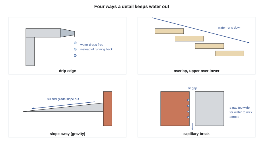
- Overlap, upper over lower: every layer that sheds water must lap over the layer below it, like shingles, so water running down is always directed outward. A flashing tucked behind the membrane below it, rather than in front, will funnel water into the wall.
- Slope: horizontal surfaces collect water. Sills, copings, ledges and the ground at the base of walls should slope away from the building, typically at least 1 in 50 and more on exposed sills.
- Drip: water clings to and runs along the underside of horizontal surfaces. A drip, a downturned edge or groove on the underside of a projection, makes the water drop free before it reaches the wall.
- Capillary break: water wicks through narrow cracks and porous materials. An air gap of about 6 mm or more, or a non-absorbent layer, stops it.
- End dams and back dams: flashings under windows and sills turn up at the ends and back so water collected on them runs out to the face, not off the ends into the wall.
- Redundancy: assume the first line of defence will leak somewhere and give the water a second line and a way out.
Other principles concern movement and construction rather than water.
- Allow for movement: Lessons 2 to 7 showed shrinkage, expansion, deflection and creep. Joints must let materials move without tearing membranes or cracking finishes.
- Allow for tolerance: nothing is built exactly to dimension. Concrete, steel and masonry each have tolerances, and details must absorb them.
- Think about sequence: who installs what, in what order, and can each layer be installed and inspected without damaging the one before it?
- Check compatibility: some materials attack each other. Copper corrodes zinc (Lesson 5); some sealants do not stick to some membranes; bitumen softens some plastics; treated wood corrodes plain steel.
- Plan for maintenance: sealants, coatings and some membranes will need renewing; make them reachable.
Tolerances
Every material and trade has its own tolerances. A cast-in-place concrete wall may be out of plumb by 6 to 10 mm over a storey and out of position by more; steel frames have erection tolerances; masonry openings vary; windows are made to a fraction of that. Where a precise element meets an imprecise one, the joint must take up the difference. A window installed in a masonry opening needs a shim space of about 10 to 20 mm around the frame, filled with backer rod and sealant outside and low-expansion foam inside, with the air barrier sealed across it.
# Will the window fit? Worst-case and statistical sums of tolerances at a masonry opening
opening, frame = 1210, 1180       # nominal opening width and window frame width, mm
tols = {"masonry opening": 6, "window frame": 2, "window placement": 3}   # plus or minus, mm
nominal_gap = (opening - frame) / 2
worst = sum(tols.values())
rss = sum(t ** 2 for t in tols.values()) ** 0.5
print(f"Nominal shim space each side: {nominal_gap:.1f} mm")
print(f"Worst-case variation: +/- {worst:.1f} mm  -> smallest gap {nominal_gap - worst:.1f} mm")
print(f"Statistical (root-sum-square) variation: +/- {rss:.1f} mm -> smallest likely gap {nominal_gap - rss:.1f} mm")
print("Minimum gap needed for backer rod and sealant:", 6, "mm")Nominal shim space each side: 15.0 mm Worst-case variation: +/- 11.0 mm -> smallest gap 4.0 mm Statistical (root-sum-square) variation: +/- 7.0 mm -> smallest likely gap 8.0 mm Minimum gap needed for backer rod and sealant: 6 mm
The worst case, every tolerance at its limit in the same direction, leaves too small a gap for a proper sealant joint; the statistical sum, which assumes the errors are independent and rarely all extreme together, leaves enough. Detailers usually design for something between the two, and they avoid details that work only if everything is perfect. Here, a slightly larger opening or a narrower frame would make the joint safe even in the worst case, and the cost of doing so on drawings is nothing.
Thermal bridges
Insulation works only where it is continuous. Structural elements that pass through it, studs, concrete slab edges, balcony slabs, steel beams, window frames, clips and girts that hold cladding, conduct heat around the insulation. These thermal bridges lower the effective insulating value of the wall, make cold spots on the interior where condensation and mould can form, and in prairie winters can cause frost on inside surfaces. Steel is the worst offender because of its high conductivity, but even wood studs, at a quarter or so of the wall area in a typical frame, reduce a wall's insulating value noticeably.
Energy codes now account for thermal bridges by asking designers to calculate the effective thermal resistance of the whole assembly rather than the nominal value of the insulation. The simplest method is the parallel path method: the wall is divided into areas through the studs and through the insulation, each area's resistance is calculated, and the heat flows are added. More complete methods add the heat lost through linear bridges, such as slab edges and window perimeters, and point bridges, such as clips.
# Effective thermal resistance of the hub wall by the parallel path method (RSI, m2 K/W)
films = 0.15            # inside and outside air films
gypsum, sheathing, cavity_air = 0.08, 0.11, 0.15
batt, stud = 3.52, 1.19   # resistance through the batt and through a solid stud of the same depth
framing = 0.23             # share of wall area that is framing (studs, plates, headers)
def wall(ext):
    common = films + gypsum + sheathing + cavity_air + ext
    r_cavity = common + batt
    r_framing = common + stud
    u = framing / r_framing + (1 - framing) / r_cavity     # heat flows add in parallel
    return 1 / u, common + batt
for ext, label in ((0, "no exterior insulation"), (1.06, "38 mm exterior mineral wool"), (2.12, "76 mm exterior mineral wool")):
    eff, nominal = wall(ext)
    print(f"{label:<34} nominal {nominal:5.2f}  effective {eff:5.2f}  ({100 * eff / nominal:.0f}% of nominal)")
# Clips that hold the cladding through the exterior insulation add point bridges
chi, clips_per_area = 0.004, 2.0
eff2, _ = wall(2.12)
u_clips = 1 / eff2 + chi * clips_per_area
print(f"With cladding clips: effective {1 / u_clips:.2f}")no exterior insulation nominal 4.01 effective 3.04 (76% of nominal) 38 mm exterior mineral wool nominal 5.07 effective 4.24 (84% of nominal) 76 mm exterior mineral wool nominal 6.13 effective 5.37 (88% of nominal) With cladding clips: effective 5.15
The calculation shows why continuous exterior insulation has become standard in cold climates. It insulates over the studs, so the framing bridges matter less; it keeps the sheathing warmer, which reduces condensation risk; and it can be supported by clips designed to minimize their own thermal bridging. It also moves the dew point outward, so the vapour control layer inside can sometimes be more permeable, letting the wall dry both ways.
Transitions
Vasić asks the students to list the transitions on their community hub's walls, and they are surprised by the length of the list: wall to foundation; brick base to wood cladding; wall to window sill, jamb and head; wall to door; wall to roof at eave and parapet; wall to the glass corner of the commons; and wall to the projecting canopy. Each needs a large-scale drawing showing how every control layer continues from one assembly to the next.
Window installation is the transition that fails most often, and it shows all the principles at work. The rough opening is lined with a sloped sill pan flashing with end dams and a back dam, lapped over the water-resistive barrier below. The window sits in the opening on shims, leaving a gap at the sill so water in the pan can drain out. The jambs are flashed with membrane strips that lap over the sill pan, and the head flashing laps over the jamb flashings and is tucked behind the water-resistive barrier above. The air barrier is sealed to the window frame all around on the inside. Outside, the cladding stops short of the frame with a sealant joint and a drip at the head. The order of laps, from bottom to top, is everything.
Drawing details
A construction detail is a large-scale drawing, typically at 1:5 or 1:10, that shows how an assembly or transition is built. Good details show every layer with its thickness, the fasteners and supports, the laps and slopes, the sealant joints with backer rod and the sequence, and they trace each control layer continuously with a coloured line, one hue for each layer. Vasić's test is the pencil test: with a pencil, can you trace the water control layer, then the air control layer, then the thermal layer, from one side of the detail to the other without lifting the pencil? Wherever the pencil must jump, the building will leak.
The students also learn the habit of three-dimensional thinking. Most details are drawn as sections, but leaks happen at corners where three planes meet: the end of a sill flashing, the corner of a parapet, the point where a window head flashing meets a jamb. Sketching these corners in axonometric, or folding a paper model of the flashing, reveals problems that sections hide.
Worked problem
Detailing the hub window above the brick base
On the hub's hall wall, the brick base rises to sill height and the wood cladding above it is interrupted by tall windows. Describe the layers at the window sill, from outside in.
Show solution
- The brick base is capped by a sloped precast sill projecting beyond the face of the brick, with a drip on its underside.
- Below the precast sill, a through-wall flashing with end dams carries water from the cavity behind the brick out over the brick face, with weeps.
- At the window, a sloped sill pan with a back dam and end dams laps over the water-resistive barrier of the backup wall and drains outward onto the precast sill.
- The window frame sits on shims above the pan; a sealant joint with backer rod closes the gap between frame and precast sill on the outside, leaving the pan able to drain.
- Inside, the air barrier is sealed to the frame and the gap is filled with low-expansion foam; the exterior insulation is carried up to the frame to limit the thermal bridge.
Answer: Two lines of defence at the sill, the precast sill and the drained pan, with laps directing every drop outward, continuous air sealing inside and insulation brought to the frame.
Exercise 9: assemblies and detailing
- Draw a 1:5 section through the sill, jamb and head of a window in your community hub wall, tracing each control layer in its own hue.
- Sketch in axonometric the corner where the sill pan meets the jamb flashing and show the end dam.
- Calculate the effective thermal resistance of your hub wall with the code above, and test the effect of adding or removing exterior insulation.
- List the tolerances that meet at one of your details and show how the joint absorbs them.
- Apply the pencil test to a published detail from a manufacturer and report any breaks in the control layers.
Common mistakes
MistakeSealing a window to the cladding with a single bead of sealant and no flashing.
InsteadProvide a sill pan, flashings lapped shingle-fashion and a sealant joint as a secondary seal.
MistakeLapping flashings the wrong way.
InsteadAlways lap upper layers over lower layers so water is directed outward.
MistakeDrawing details as if everything will be built exactly to size.
InsteadDesign joints that absorb the tolerances of each trade.
MistakeCounting the nominal value of insulation.
InsteadCalculate effective thermal resistance, including studs, clips and slab edges.
MistakeDetailing only in section.
InsteadCheck corners and ends in three dimensions, where most leaks happen.
Summary and key terms
- Assemblies combine materials to perform together; most failures happen at joints and transitions.
- The water, air, vapour and thermal control layers must be continuous across every transition.
- Deflection, drainage, drying and durability manage water; rainscreens put these into practice.
- Detailing principles include overlap, slope, drip, capillary break, end dams, redundancy, movement, tolerance, sequence, compatibility and maintenance.
- Thermal bridges reduce effective insulation; continuous exterior insulation reduces their effect.
- Large-scale details should let a pencil trace every control layer without a break.
- Assembly
- A set of materials combined to perform together, such as a wall or roof.
- Rainscreen
- Cladding with a drained, ventilated cavity behind it and a second line of defence.
- Flashing
- A thin, impervious sheet that directs water out of an assembly.
- End dam
- An upturned end of a flashing that stops water running off its ends into the wall.
- Thermal bridge
- A path of higher conductivity through the insulation.
- Tolerance
- The permitted variation of a dimension in construction.
Practice problems
Work each problem on paper first, then reveal the answer to check.
Why must a head flashing over a window be tucked behind the water-resistive barrier above it?
Show answer
So water running down the barrier is directed onto the flashing and out, not behind it.
A wall has studs over 23% of its area. Why does its effective insulating value fall below that of the batts?
Show answer
Wood conducts heat more than insulation, so heat bypasses the batts through the studs.
What does a drip do?
Show answer
It makes water drop free from the underside of a projection instead of running back to the wall.
Name three transitions where control layers commonly fail.
Show answer
Wall to window, wall to roof and wall to foundation (others are acceptable).
Why is a statistical tolerance sum smaller than the worst case?
Show answer
It is unlikely that every element will be at its extreme in the same direction at once.
Lesson quiz · 5 questions
Score 60% or more to complete this lesson.
Create a free account to save your progress, take quizzes and earn a certificate.