
ARCH-200 · Lesson 11 of 12 · 23 min
Technical integration
In January the studio fills with consultants. Haddad has asked a mechanical engineer, Kofi Mensah, an electrical engineer and an acoustician to spend an afternoon each with the class. Mensah begins by unrolling a plain pencil section of a school he engineered. Instead, he points: here is the air coming in, here it is warmed, here it is delivered to the classrooms, here it returns, here the heat is recovered before it goes out. Pipes, ducts, wires and sprinklers fill every space above the ceilings and in the walls. 'Architects draw the building,' he says. 'We fill it. The good buildings are the ones where you made room for us at the start, so we didn't have to fight you for every inch at the end.'
What technical integration means
A building is a set of systems that must work together: structure, envelope, heating, cooling, ventilation, plumbing, electrical power, lighting, communications, fire protection, vertical transportation and acoustics. Technical integration is the design work of fitting these systems into the building so that each performs well, none compromises another and the whole supports the architectural idea. It is a central skill of architects. A beautiful plan that leaves no room for ducts, a structure that blocks the only route for a sewer pipe or a roof with nowhere to put the equipment will be fixed during construction, usually badly and expensively.
Integration happens at three scales. At the scale of the whole building, systems need rooms, shafts and routes: a mechanical room, an electrical room, risers between floors and roof space for equipment. At the scale of a floor, they need zones above ceilings, below floors or within walls. At the scale of a detail, they need openings, supports and access panels. The architect's job is to plan the first two scales during design development so that the third can be solved in the construction documents.
Heating, ventilation and cooling for a cold climate
Mensah describes the systems he would propose for the hub. The building's heating will come from heat pumps, which move heat rather than burn fuel and are increasingly used in cold climates to cut carbon emissions. A ground-source system would draw heat from a field of boreholes under the yard or the parking area; an air-source system would use outdoor units on the roof or at grade, with a backup for the coldest days. Heat would reach the rooms as warm water for radiant floors, which suit the playrooms and the gallery, and as warmed air.
Ventilation is the supply of outdoor air to dilute the carbon dioxide, moisture, odours and pollutants that people and activities produce. In a cold climate, heating that outdoor air is a large part of the building's energy use, so the exhaust air should pass through a heat recovery ventilator or energy recovery ventilator, which transfers heat from the outgoing stale air to the incoming fresh air without mixing them. Codes and standards set minimum ventilation rates, usually combining an amount per person and an amount per unit of floor area, which depend on the use. A gym full of players, a daycare full of children and a hall full of diners all need more air per person than a library.
# Outdoor air for the main spaces (rates per person plus per floor area, typical of ventilation standards)
spaces = {   # name: (people, floor area m2, rate per person, rate per area)
    "gym in use":       (40, 520, 10, 0.9),
    "hall, dinner":     (350, 520, 3.8, 0.3),
    "daycare":          (56, 290, 5, 0.9),
    "library":          (120, 450, 2.5, 0.6),
}
for name, (people, area, rp, ra) in spaces.items():
    q = people * rp + area * ra
    duct = q / 1000 / 4.0                     # cross-section of a main duct at the design velocity
    print(f"{name:<13} outdoor air {q:7.0f} L/s, main duct about {duct:.2f} m2")
# Hall air is needed only when the hall is busy; demand-controlled ventilation saves energy.gym in use outdoor air 868 L/s, main duct about 0.22 m2 hall, dinner outdoor air 1486 L/s, main duct about 0.37 m2 daycare outdoor air 541 L/s, main duct about 0.14 m2 library outdoor air 570 L/s, main duct about 0.14 m2
The numbers show which spaces drive the system. The hall at a dinner needs the most outdoor air, and its main duct is the largest: roughly 0.4 m² in cross-section, which with insulation and clearances means a duct about 900 by 600 mm or larger running across the hall. Because the hall is often empty, Mensah proposes demand-controlled ventilation, in which carbon dioxide sensors adjust the airflow to the number of people actually present. For a tall hall, he suggests displacement ventilation: cool fresh air introduced slowly at low level, rising as it warms around people, and extracted at the ceiling. It is quiet and efficient, which suits both a gym and a concert, and needs low-level diffusers that Callum must place along the walls where they will not be hit by balls.
Cooling is a smaller load in this climate, but summer heat waves and crowded halls make some cooling necessary. The same heat pumps can run in reverse. Night flushing, opening windows or running the fans at night to cool the building's mass, and the shading designed in Lesson 8 reduce the cooling needed. Operable windows in the playrooms and library let users take control on mild days, and Rita Moreau is firm that the children must be able to have fresh air through open windows in spring and autumn.
Space for the systems
Mensah asks for four things. A mechanical room of about 90 m², at grade, with a double door to the outside for replacing equipment, close to the centre of the building so that ducts and pipes are short. An electrical room of about 20 m² near the street, where the utility's service enters. Vertical shafts, at least two, each about 2 by 1.5 m, to carry ducts and pipes from the mechanical room to the upper floor and the roof. And a ceiling zone in every major space deep enough for ducts, pipes, sprinklers and lights to cross the structure.
Callum places the mechanical room in the servant band between the hall and the wing, where it is central, at grade and reachable from a service lay-by on the avenue for deliveries. The shafts rise in the stair and elevator cores, which already break the plan at the junctions. The electrical room goes beside the commons on the street side, where the utility can reach it without crossing the site. On the roof, he groups the heat pump units and the ventilators behind a screen at the centre of the bar, where they are invisible from the street and away from the library's roof monitors. He checks the snow load and the access route for maintenance, which must not cross the monitors.
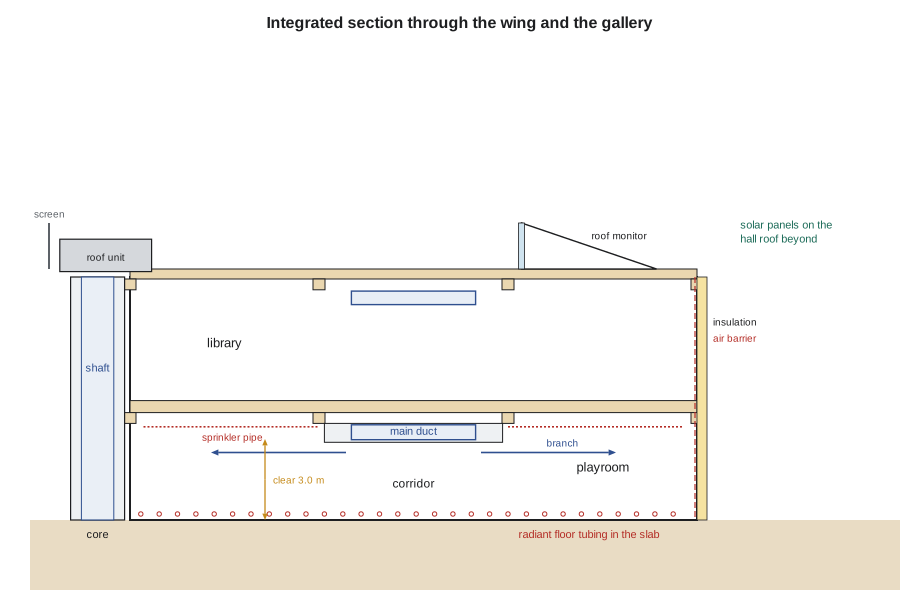
Within each floor, systems need a zone. Where a ceiling hides them, the zone lies between the structure and the ceiling. Where the structure is exposed, as in the library and daycare, there is no ceiling to hide behind, and every duct, pipe and wire is visible. This is harder to design and more expensive to build neatly, but it can be handsome when systems run in orderly lines parallel to the structure. Callum decides to run the main ducts in the wing's middle row of bays, along the corridor, under a lowered ceiling there, and to supply the playrooms and library from that spine with short branches. The rooms themselves keep their exposed timber ceilings.
Plumbing and fire protection
Plumbing is less flexible than ductwork, because drainage pipes rely on gravity and must slope continuously downward to the sewer. Washrooms, kitchens and other wet rooms should therefore be stacked above one another and grouped near the sewer connection, with straight vertical stacks and short horizontal runs. In a building with a slab on grade, drainage pipes run below the slab, and their routes must be planned before the slab is poured. Callum stacks the upper-floor washrooms over the ground-floor washrooms in the cores. The community kitchen needs a grease interceptor, a tank that captures fats before they reach the sewer, placed where it can be pumped out from the service lay-by.
The hub will be fully sprinklered, as the code analysis assumed. Sprinkler pipes run from a fire service connection at the street to the riser room, then horizontally across every space. In exposed timber ceilings, sprinkler pipes and heads are visible and must be laid out to align with the structure, which takes coordination. The fire alarm system, emergency lighting and exit signs also need power, wiring routes and careful placement. A fire department connection, where firefighters can pump extra water into the system, must be on the street side and clearly visible.
Electrical, lighting and renewable energy
Electrical power arrives from the utility at the electrical room and is distributed to panels on each floor. Lighting, increasingly using efficient LED fixtures with controls that dim them when daylight is sufficient or switch them off when rooms are empty, works with the daylighting strategy of Lesson 8. Data and communications cabling reaches every room. The electrical engineer also asks for space for a future battery and for chargers for electric vehicles in the parking area.
The hall's large flat roof is an obvious place for solar photovoltaic panels. At this latitude, panels tilted toward the south produce well in spring and summer and less in winter, when the days are short and snow may cover them. Mensah estimates that a system covering most of the hall roof could supply a significant share of the building's annual electricity, especially if the building is efficient. Callum sets aside the hall roof for panels and checks that the parapets, the roof equipment and the library's monitors do not shade them.
Acoustics
The acoustician, Claire Beaulieu, focuses on two problems. The first is sound isolation: keeping the noise of the gym and hall out of the library, the daycare's sleep room and the meeting rooms. Sound travels through air gaps, through walls and floors and along the structure. Walls between noisy and quiet spaces need mass, separated layers and airtight construction, rated by their sound transmission class; doors need seals; ducts that connect noisy and quiet rooms need silencers or long, lined routes. The best defence is planning: putting buffers such as storage rooms, corridors and washrooms between the noisiest and quietest rooms, as the adjacency matrix in Lesson 4 suggested.
The second problem is room acoustics, the way sound behaves inside a room. A gym with hard walls, a hard floor and a hard roof is very reverberant; sound lingers for several seconds, so speech becomes unintelligible and a crowd becomes deafening. Absorptive panels on the upper walls and the underside of the roof, out of reach of balls, reduce the reverberation time to something tolerable for both games and community dinners. In the library and daycare, exposed timber ceilings are hard surfaces too; Beaulieu suggests absorptive panels between the beams and soft flooring in the children's areas.
# Reverberation time of the hall by Sabine's formula: RT = 0.161 V / A (metric) or 0.049 V / A (imperial)
volume = 24 * 22 * 8
surfaces = {   # name: (area, absorption coefficient at mid frequencies)
    "wood sports floor": (24 * 22, 0.10),
    "roof deck, bare": (24 * 22, 0.05),
    "walls, painted block": (2 * (24 + 22) * 8, 0.05),
}
def rt(surf):
    a = sum(area * coef for area, coef in surf.values())
    return 0.161 * volume / a

print(f"Hall volume {volume:,.0f} m3")
print(f"Bare hall:             reverberation time about {rt(surfaces):.1f} s")
treated = dict(surfaces)
treated["roof deck, bare"] = (24 * 22 * 0.3, 0.05)
treated["absorptive roof panels"] = (24 * 22 * 0.7, 0.80)
treated["upper wall panels"] = (2 * (24 + 22) * 3, 0.80)
treated["walls, painted block"] = (2 * (24 + 22) * (8 - 3), 0.05)
print(f"With roof and wall panels: about {rt(treated):.1f} s")Hall volume 4,224 m3 Bare hall: reverberation time about 5.9 s With roof and wall panels: about 1.1 s
The bare hall would have a reverberation time of several seconds, like a cathedral. With absorptive panels on most of the roof and the upper walls, it falls to around one second, suitable for sport and speech. Callum had planned to leave the hall's walls as bare painted block. He now designs the upper walls as a continuous band of wood slats over acoustic insulation, which adds warmth and becomes one of the hall's defining features.
Coordination
In practice, the architect and the engineers coordinate their systems in a shared digital model, a process covered in Digital Design and BIM, and check for clashes, places where two elements occupy the same space. But coordination begins with simple drawings: an integrated section through the most congested part of the building, showing structure, envelope, ceilings, ducts, pipes and lights at their real sizes. Mensah asks each student to draw one. Callum's section through the gallery reveals that the main duct from the mechanical room must pass under a glulam beam and over the gallery's ceiling, leaving only 2.6 m of clear height under it. He adjusts the beam depth, lowers the duct into a bulkhead along the inner wall of the gallery, and raises the gallery ceiling elsewhere. Each of these is a small change; together they make the gallery feel as tall as he intended.
Worked problem
Placing the roof equipment
Mensah's preliminary layout puts the heat pump units on the library roof, directly above the reading room, because it is the shortest route to the shaft. What problems does this create, and where should they go?
Show solution
- Noise and vibration from compressors and fans would reach the reading room through the roof structure.
- Equipment would shade the north-facing roof monitors and could block their light.
- Maintenance workers would have to cross the monitors, risking damage and leaks.
- Snow would drift against the equipment and the monitors, adding load where the roof is most complex.
- A better place is the roof over the servant band between the hall and the wing, directly above the mechanical room and the shaft, behind a screen, where noise falls on storage and washrooms and no roof monitors are nearby.
Answer: Group the equipment over the servant band, above the mechanical room, behind a screen; keep it away from the library and its monitors.
Exercise 11: technical integration
- Locate the mechanical room, electrical room, shafts, roof equipment and fire service connection on your plans.
- Calculate the outdoor air needed for your four largest spaces and estimate the sizes of the main ducts.
- Stack wet rooms and plan the main drainage route to the sewer.
- Draw an integrated section at 1:50 through the most congested part of your building, showing every system at its real size.
- Identify the noisiest and quietest rooms and describe how you will separate them.
- Estimate the reverberation time of your hall and propose acoustic treatment.
Self-critique checklist
- Have I made room for every system at the scale of the building, the floor and the detail?
- Does my integrated section have realistic clear heights after the systems are added?
- Are noisy and quiet spaces separated by planning as well as by construction?
- Does the roof work for equipment, maintenance, snow and daylight together?
Common mistakes
MistakeLeaving building systems for the engineers to fit in later.
InsteadPlan rooms, shafts and zones for systems during design development.
MistakePlacing noisy equipment above quiet rooms.
InsteadGroup equipment over servant spaces and away from sensitive rooms.
MistakeScattering washrooms so pipes cannot stack.
InsteadStack wet rooms and keep drainage runs short and straight.
MistakeLeaving a gym or hall acoustically bare.
InsteadAdd absorption on the upper walls and roof to control reverberation.
MistakeAssuming exposed structure needs no coordination.
InsteadLay out ducts, pipes and sprinklers in orderly lines with the structure.
Summary and key terms
- Technical integration fits structure, envelope and building systems together so each performs well and supports the design idea.
- Heat pumps, heat recovery ventilation, radiant floors and demand-controlled ventilation suit a cold-climate community building.
- Systems need rooms, shafts, roof space and ceiling zones planned early.
- Plumbing relies on gravity, so wet rooms should be stacked and grouped.
- Acoustics involves both isolating noisy spaces and controlling reverberation inside rooms.
- Heat recovery ventilator
- A device that transfers heat from exhaust air to incoming fresh air.
- Demand-controlled ventilation
- Ventilation that varies with the number of occupants, usually by sensing carbon dioxide.
- Displacement ventilation
- Supplying cool air slowly at low level so it rises as it warms around people.
- Shaft
- A vertical enclosure carrying ducts, pipes or wires between floors.
- Reverberation time
- The time it takes for sound in a room to fade by a set amount after the source stops.
- Sound transmission class
- A rating of how well a wall or floor blocks airborne sound.
Practice problems
Work each problem on paper first, then reveal the answer to check.
Why should the mechanical room be near the centre of the building?
Show answer
To keep ducts and pipes short, saving space, cost and energy.
What does a heat recovery ventilator do?
Show answer
It transfers heat from outgoing stale air to incoming fresh air without mixing them.
Why stack washrooms on two floors?
Show answer
Drainage relies on gravity, so stacked wet rooms allow straight vertical pipes and short runs.
A hall has a reverberation time of four seconds. Why is that a problem?
Show answer
Speech becomes hard to understand and crowd noise builds up; around one second suits sport and speech.
Where should rooftop equipment go in Callum's scheme, and why?
Show answer
Over the servant band above the mechanical room, away from quiet rooms and the library's roof monitors.
Lesson quiz · 5 questions
Score 60% or more to complete this lesson.
Create a free account to save your progress, take quizzes and earn a certificate.