
AERO-340 · Lesson 8 of 12 · 27 min
Compressors
The compressor is the hardest part of a gas turbine to design well. It works against the natural tendency of air to flow from high pressure to low, and if it is pushed too hard it stalls, sometimes violently. The Brayton analysis of Lesson 3 needed only a pressure ratio and an efficiency; this lesson looks inside, at how the blades produce that pressure rise and what limits them. Arjun spends two weeks with the compressor specialists at the engine maker supplying the Swift 900, and Dr. Nakamura asks him to come back able to explain three things to the rest of the group: where the work goes in, why a core needs so many stages, and what the surge margin on the engine's performance deck really means.
Axial and centrifugal compressors
Axial compressors move the air parallel to the shaft through alternating rows of rotating blades and stationary vanes. Each rotor-stator pair is a stage. Axial machines handle large flows in a small frontal area and reach high efficiencies, 0.88 to 0.92 for a whole compressor, so they dominate large engines. Centrifugal compressors draw air in at the hub and fling it outward through an impeller, then slow it in a diffuser. A single centrifugal stage can reach a pressure ratio of 4 to 8, far more than an axial stage, and it is rugged and tolerant of dirt and damage, but it is bulky in diameter for its flow. Small engines, including the Tern's turboshaft and many turboprops and helicopter engines, use centrifugal stages, often behind a few axial ones.
Velocity triangles and the Euler equation
The work a rotor does on the air comes from changing the air's swirl, its tangential velocity. Applying the moment of momentum to the flow through a rotor gives the Euler turbomachinery equation, the foundation of every compressor and turbine calculation:
where \(U\) is the blade speed and \(C_\theta\) the tangential component of the absolute velocity at rotor inlet (1) and exit (2). The work depends on blade speed and on how much the rotor turns the flow. Velocity triangles connect the absolute velocity \(C\), the blade speed \(U\) and the velocity relative to the blade \(W\), so that \(\vec C = \vec U + \vec W\). The rotor blades are shaped to turn the relative flow; the stator vanes then remove the swirl the rotor added and recover pressure by slowing the flow, ready for the next stage.
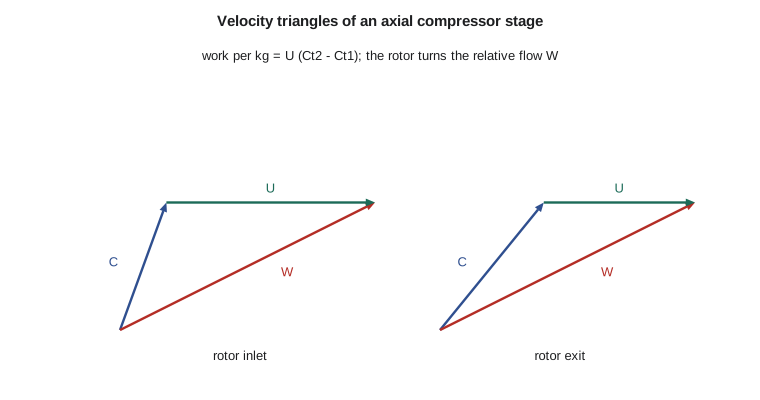
Three non-dimensional numbers describe a stage. The flow coefficient \(\phi = C_x/U\) compares axial velocity to blade speed. The stage loading \(\psi = \Delta h_0/U^2\) compares the work to the square of blade speed; axial compressor stages typically run at 0.3 to 0.5. The degree of reaction is the fraction of the stage's static enthalpy rise that happens in the rotor, usually around 0.5 to 0.7. A practical limit on how much a blade row can slow the relative flow is the de Haller ratio \(W_2/W_1\), which should stay above about 0.72; slow it more and the boundary layer on the blade suction surface separates.
# Velocity triangles of a repeating axial compressor stage, its pressure ratio and loading,
# how many such stages a core of pressure ratio 24 needs, and a centrifugal stage for the
# Tern's turboshaft for comparison.
import math
cp, g = 1005.0, 1.4
U, Cx, a1 = 340.0, 170.0, math.radians(20)     # blade speed, axial velocity, inlet absolute flow angle
Ct1 = Cx * math.tan(a1)
beta1 = math.atan((U - Ct1) / Cx)              # relative inlet angle
W1 = math.hypot(Cx, U - Ct1)
dh = 26000.0                                   # J/kg, chosen stage work
Ct2 = Ct1 + dh / U                             # Euler: dh = U (Ct2 - Ct1)
beta2 = math.atan((U - Ct2) / Cx); W2 = math.hypot(Cx, U - Ct2)
psi, phi = dh / U**2, Cx / U
R = 1 - (Ct1 + Ct2) / (2 * U)                  # degree of reaction (repeating stage)
dH = W2 / W1                                   # de Haller ratio, keep above about 0.72
print(f"rotor relative angles: in {math.degrees(beta1):4.1f} deg, out {math.degrees(beta2):4.1f} deg (turning {math.degrees(beta1-beta2):4.1f} deg)")
print(f"flow coefficient {phi:.2f}, stage loading {psi:.3f}, reaction {R:.2f}, de Haller ratio {dH:.2f}")
T_in, eta_s = 300.0, 0.89
pr_stage = (1 + eta_s * dh / (cp * T_in)) ** (g / (g - 1))
print(f"stage pressure ratio at 300 K inlet: {pr_stage:.3f}")
T, pr, n = 300.0, 1.0, 0
while pr < 24:
    pr *= (1 + eta_s * dh / (cp * T)) ** (g / (g - 1)); T += dh / cp; n += 1
print(f"stages of this loading for pressure ratio 24: {n} (overall {pr:.1f}, exit {T:.0f} K)")
print("so real cores split the work between fan, booster and a high-speed spool with higher blade speeds")
# centrifugal stage: work = slip factor * U2^2 (radial blades, no inlet swirl)
U2, sigma = 520.0, 0.90
w = sigma * U2**2
pr_c = (1 + 0.80 * w / (cp * 288.15)) ** (g / (g - 1))
print(f"\none centrifugal stage, tip speed {U2:.0f} m/s: work {w/1000:.0f} kJ/kg, pressure ratio about {pr_c:.1f}")rotor relative angles: in 58.6 deg, out 49.9 deg (turning 8.7 deg) flow coefficient 0.50, stage loading 0.225, reaction 0.71, de Haller ratio 0.81 stage pressure ratio at 300 K inlet: 1.295 stages of this loading for pressure ratio 24: 21 (overall 25.2, exit 843 K) so real cores split the work between fan, booster and a high-speed spool with higher blade speeds one centrifugal stage, tip speed 520 m/s: work 243 kJ/kg, pressure ratio about 6.0
The program puts the stage at a blade speed of 340 m/s, axial velocity 170 m/s and inlet swirl angle 20 degrees, doing 26 kJ/kg. The rotor turns the relative flow by only 8.7 degrees, with a flow coefficient of 0.50, loading of 0.225, reaction of 0.71 and a comfortable de Haller ratio of 0.81. The stage pressure ratio is 1.30 at 300 K. Repeating that stage would need 21 stages to reach a pressure ratio of 24, because each stage gives less pressure ratio as the air heats up. That is why real cores do not use one long uniform compressor: they split the work between the fan, a few booster stages on the low-pressure spool and a high-pressure compressor on its own fast spool, with higher blade speeds and more loading per stage, so that 10 to 14 compressor stages in total reach pressure ratios of 30 to 50.
The centrifugal stage at a tip speed of 520 m/s does 243 kJ/kg and reaches a pressure ratio of about 6 in one step, almost nine times the work of the axial stage. That is why the Tern's turboshaft gets its pressure ratio of 10 from just two centrifugal stages.
Compressor maps, stall and surge
A compressor's performance is summarized on a map of pressure ratio against corrected mass flow, with lines of constant corrected speed. Corrected values, \(\dot m\sqrt{\theta}/\delta\) and \(N/\sqrt{\theta}\), where \(\theta\) and \(\delta\) are inlet total temperature and pressure divided by standard sea-level values, make one map work at any altitude and temperature. The engine runs along an operating line set by the turbine and nozzle downstream. Above and to the left on the map lies the surge line.
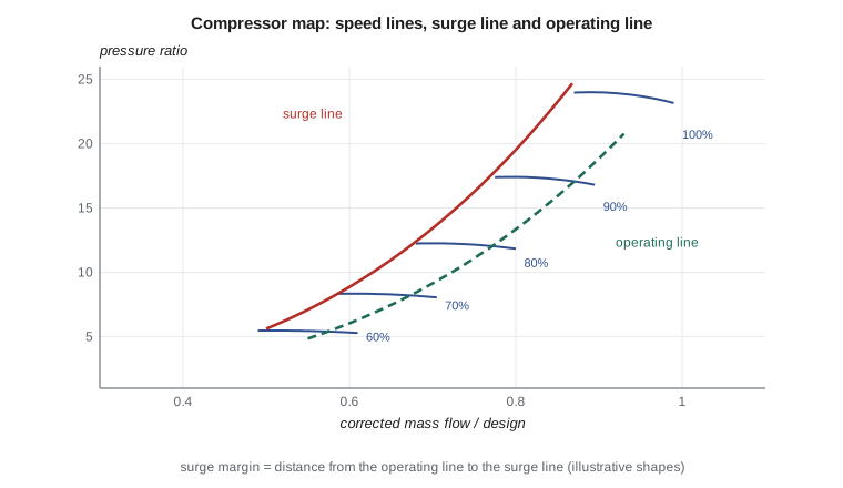
Rotating stall occurs when some blade passages stall and the stalled cells rotate around the annulus at part of the shaft speed; it causes vibration and loss of performance. Surge is a breakdown of the whole flow: the compressor can no longer hold the pressure behind it, the flow reverses through the machine, often with a bang and flames from the inlet, and then recovers, repeating at a few cycles per second until the engine is throttled back. Surge can damage blades and must be avoided. Engines are designed with a surge margin, typically 15 to 25 percent, between the operating line and the surge line, to allow for inlet distortion, rapid throttle movements and engine deterioration. Bleed valves that dump air at low speed, variable stator vanes that change blade angles at part speed, and multiple spools all help keep the stages matched over the speed range.
| Feature | Axial | Centrifugal |
|---|---|---|
| Pressure ratio per stage | about 1.2 to 1.5 | about 4 to 8 |
| Efficiency | about 0.88 to 0.92 | about 0.80 to 0.86 |
| Frontal area for flow | small | large |
| Robustness to damage and dirt | lower | higher |
| Typical use | large turbofans, high-pressure spools | small turboshafts, turboprops, final stages of small engines |
Worked problem
Euler work
A rotor with a mean blade speed of 300 m/s raises the absolute swirl from 60 to 150 m/s. Find the work per kilogram and the temperature rise.
Show solution
- \(\Delta h_0 = 300 \times (150 - 60) = 27\,000\) J/kg.
- \(\Delta T_0 = 27\,000/1005 = 26.9\) K.
Answer: 27 kJ/kg and about 27 K of total temperature rise.
Worked problem
Stage loading and flow coefficient
For the stage above, the axial velocity is 160 m/s. Find the stage loading and flow coefficient.
Show solution
- \(\psi = 27\,000/300^2 = 0.30\).
- \(\phi = 160/300 = 0.53\).
Answer: A loading of 0.30 and flow coefficient of 0.53, both normal values.
Worked problem
Corrected flow
A fan passes 26 kg/s at cruise where the inlet total temperature is 245 K and total pressure 27.1 kPa. Find the corrected mass flow.
Show solution
- \(\theta = 245/288.15 = 0.850\), \(\delta = 27.1/101.325 = 0.267\).
- \(\dot m_c = 26\sqrt{0.850}/0.267 = 26 \times 0.922/0.267 = 89.8\) kg/s.
Answer: About 90 kg/s corrected, close to the fan's take-off value, which is why cruise and take-off fall near the same part of the map.
Damage, deterioration and fan blades
Compressors wear in service. Erosion from sand and dust rounds the leading edges and thins the blades, fouling roughens the surfaces, and tip clearances grow as seals rub. Each effect lowers efficiency and moves the surge line closer to the operating line. Operators wash compressors periodically with water or cleaning solutions to recover some of the lost performance, and engine monitoring trends exhaust gas temperature, which rises as the compressor and turbine deteriorate.
Fan blades face a further hazard: foreign objects and birds. Certification under the engine standards in Chapter 533 of the Transport Canada Airworthiness Manual requires the engine to tolerate ingestion of birds of specified sizes and numbers, hail and ice, and to contain a fan blade released at full speed, with the engine shut down safely. Modern fans use wide-chord titanium or composite blades with metal leading edges, designed to survive impacts and to fail predictably if they must. The blade-off test, run once on a real engine before certification, is one of the most dramatic events in an engine programme.
Worked problem
Clearance effect
A rule of thumb is that each 1 percent increase in tip clearance, as a fraction of blade height, costs about 1.5 percent of stage efficiency. A stage with 30 mm blades opens its clearance from 0.3 to 0.6 mm. Estimate the efficiency loss.
Show solution
- Clearance change \(= 0.3/30 = 1\) percent of blade height.
- Efficiency loss \(\approx 1.5\) percentage points.
Answer: About 1.5 points of stage efficiency, which is why short blades in the rear stages of small compressors are so sensitive to clearance (illustrative rule).
Arjun comes back with his three answers. The work goes in through swirl, by the Euler equation. A core needs many stages because each axial stage can slow the relative flow only so far before its boundary layers separate. And the surge margin on the performance deck is the room the engine keeps in reserve for distortion, fast throttle movements and the wear of thousands of flights.
Common mistakes
MistakeThinking the rotor adds pressure directly.
InsteadThe rotor adds energy by changing swirl; pressure rises in both rotor and stator as the flow slows.
MistakeAssuming the stage pressure ratio stays constant through a compressor.
InsteadIt falls as the air heats up for the same work.
MistakeConfusing rotating stall with surge.
InsteadRotating stall is local and rotating; surge is a breakdown and reversal of the whole flow.
MistakeReading a compressor map with uncorrected flow and speed.
InsteadCorrected values make one map apply at all inlet conditions.
Summary and key terms
- Compressors add energy by changing the swirl of the flow, as the Euler equation states; velocity triangles relate absolute, relative and blade velocities.
- Flow coefficient, stage loading, reaction and the de Haller ratio describe a stage.
- Axial stages give modest pressure ratios at high efficiency, so cores use many stages split between spools; centrifugal stages give much higher pressure ratios in one step and suit small engines.
- Maps of pressure ratio against corrected flow show speed lines, the operating line and the surge line, and engines need a surge margin of about 15 to 25 percent, maintained with bleed valves, variable stators and multiple spools.
- Euler equation
- Work per unit mass equals blade speed times change in tangential velocity.
- Velocity triangle
- The vector relation between absolute, relative and blade velocities.
- Stage loading
- Stage work divided by blade speed squared.
- Degree of reaction
- Fraction of the stage static enthalpy rise occurring in the rotor.
- De Haller ratio
- Relative velocity ratio across a blade row; a diffusion limit.
- Surge
- Breakdown of compressor flow with reversal, causing large pressure fluctuations.
- Surge margin
- The margin between the operating line and the surge line on the compressor map.
Practice problems
Work each problem on paper first, then reveal the answer to check.
A rotor at 400 m/s mean blade speed changes swirl by 80 m/s. What is the work?
Show answer
32 kJ/kg.
In the program, raise the stage work to 32 kJ/kg. What happens to the de Haller ratio?
Show answer
It falls to about 0.77, closer to the separation limit.
Why does a long compressor need variable stator vanes?
Show answer
To keep the front and rear stages matched at part speed and avoid stall.
What is the corrected speed of a spool at 10 000 rpm with inlet total temperature 250 K?
Show answer
About 10 740 rpm.
Why are centrifugal stages common in small engines?
Show answer
High pressure ratio per stage, robustness and simplicity at small flows.
What happens to the operating point when the throttle is opened quickly?
Show answer
It moves toward the surge line temporarily, which is one reason surge margin is needed.
Lesson quiz · 5 questions
Score 60% or more to complete this lesson.
Create a free account to save your progress, take quizzes and earn a certificate.