
AERO-340 · Lesson 10 of 12 · 27 min
Turbines and cooling
The turbine takes the hot gas from the combustor and extracts the work that drives the compressor, the fan or the propeller. Lesson 3 showed that a hotter turbine inlet makes a better cycle, and turbine inlet temperatures in modern engines are now several hundred kelvin above the melting point of the nickel alloys the blades are made of. The blades survive only because they are cooled from inside, protected by ceramic coatings and made from single crystals of metal. The turbine is the part of the engine most closely tied to engine life and maintenance cost, which is why the large engine overhaul shops in Winnipeg spend so much of their effort on it. Dr. Nakamura sends Arjun to an overhaul shop to watch a high-pressure turbine being inspected before he writes the turbine section of the Swift 900 engine assessment.
Turbine stages and the Euler equation
A turbine stage is the reverse of a compressor stage. Stationary nozzle guide vanes first accelerate the gas and turn it strongly in the direction of rotation; the rotor blades then turn it back, extracting swirl, and the Euler equation gives the work:
where station 2 is the vane exit and 3 the rotor exit. Because the flow is accelerating through both rows, the boundary layers are thin and do not separate easily, so a turbine stage can take much more work than a compressor stage: stage loadings \(\psi = w_t/U^2\) of 1 to 2.5 are normal, compared with 0.3 to 0.5 for compressors. That is why one or two high-pressure turbine stages can drive a high-pressure compressor of ten stages. Turbines are designed with a small exit swirl, or a slight counter-swirl, so that little kinetic energy is lost in the leaving gas.
# Turbine stage work from velocity triangles, and the blade cooling needed to keep metal
# temperature acceptable at three turbine inlet temperatures (simple cooling-effectiveness model).
import math
cpg = 1150.0
U, Cx = 450.0, 200.0
a2 = math.radians(68)                            # nozzle guide vane exit angle
Ct2 = Cx * math.tan(a2); Ct3 = -40.0             # small counter-swirl leaving the rotor
w = U * (Ct2 - Ct3)                              # Euler work, J/kg
print(f"absolute swirl in {Ct2:.0f} m/s, out {Ct3:.0f} m/s, stage work {w/1000:.0f} kJ/kg, "
      f"loading {w/U**2:.2f}, temperature drop {w/cpg:.0f} K")
T_cool, T_metal_max = 900.0, 1300.0              # coolant from the compressor exit, allowable metal temperature, K
print("\nTIT K   cooling effectiveness needed   coolant fraction (illustrative correlation)")
for Tg in (1500, 1700, 1900):
    eps = (Tg - T_metal_max) / (Tg - T_cool)
    frac = 0.06 * eps / (1 - eps) if eps < 1 else float('inf')   # simple trend: coolant grows fast as eps -> 1
    print(f"{Tg:5d}           {eps:4.2f}                       {100*frac:4.1f} percent of core air")
print("\nevery 1 percent of air bled for cooling costs roughly 0.5 to 1 percent of cycle power (rule of thumb)")absolute swirl in 495 m/s, out -40 m/s, stage work 241 kJ/kg, loading 1.19, temperature drop 209 K TIT K cooling effectiveness needed coolant fraction (illustrative correlation) 1500 0.33 3.0 percent of core air 1700 0.50 6.0 percent of core air 1900 0.60 9.0 percent of core air every 1 percent of air bled for cooling costs roughly 0.5 to 1 percent of cycle power (rule of thumb)
With a blade speed of 450 m/s, axial velocity 200 m/s and a vane exit angle of 68 degrees, the stage in the program extracts 241 kJ/kg, a loading of 1.19, and the gas temperature drops by 209 K. That single stage could drive about nine of the compressor stages of Lesson 8. The vane exit velocity of about 530 m/s is close to sonic for gas at turbine temperatures, which is normal: high-pressure turbine vanes often run near choked, and their throat area sets the engine's flow capacity, the reason the turbine fixes the compressor's operating line.
Why turbines need cooling
Nickel-based superalloys keep their strength to about 1300 to 1400 K, and blade metal temperature must stay well below that for the blades to last thousands of hours without creep, the slow stretching of a metal under load at high temperature. A high-pressure turbine blade spinning at over 10 000 rpm carries a centrifugal load of several tonnes, so creep is the life-limiting mechanism. Turbine inlet temperatures of 1700 to 1900 K at take-off are therefore only possible with cooling. The measure of cooling performance is the cooling effectiveness
where \(T_g\) is the gas temperature, \(T_m\) the allowed metal temperature and \(T_c\) the coolant temperature, which is the compressor exit air used to cool the blade. An effectiveness of 0.5 means the blade metal sits halfway between gas and coolant temperatures.
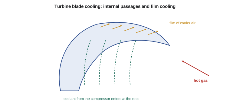
Cooling uses three main techniques, usually together. Internal convection passes compressor air through serpentine passages inside the blade, with ribs and pins to increase heat transfer. Impingement cooling directs jets of air at the inside of the leading edge, the hottest region. Film cooling lets air out through rows of small holes onto the blade surface, where it forms a thin, cooler layer between the hot gas and the metal. Over all of this, a ceramic thermal barrier coating, typically yttria-stabilised zirconia about a quarter of a millimetre thick, insulates the metal by 100 K or more. The blade itself is often cast as a single crystal, with no grain boundaries for creep to act along.
Cooling is not free. The air used comes from the compressor, has had work done on it and then bypasses the combustor, so it contributes less to the turbine than the main flow; and film cooling air mixing into the hot gas causes aerodynamic losses. The program shows how the coolant needed grows as turbine inlet temperature rises: with metal limited to 1300 K and coolant at 900 K, a 1500 K turbine needs an effectiveness of 0.33 and about 3 percent of core air; at 1700 K, 0.50 and about 6 percent; at 1900 K, 0.60 and about 9 percent. The correlation is a simple illustrative trend, but the shape is real: each extra 100 K of turbine inlet temperature costs more cooling air than the last. Engine designers balance the cycle gain from higher temperature against the cooling penalty, and real high-pressure turbines use 15 to 25 percent of core air for cooling and sealing in total.
Life, inspection and maintenance
Turbine blades are life-limited parts. Their life is lost through creep, through low-cycle fatigue as the engine starts and stops and the blades heat and cool, through oxidation and hot corrosion of the surfaces, and through coating loss. Engine makers set inspection intervals and life limits based on these mechanisms, and operators monitor exhaust gas temperature margin, the difference between the actual and the maximum allowable exhaust temperature at take-off, because it shrinks as the engine wears. When the margin runs out, the engine comes off the wing for a shop visit. At the overhaul shop, Arjun sees borescope inspection of blades through small ports in the casing, fluorescent penetrant checks for cracks, and coating restoration. The technician points out that a hot streak from one blocked fuel nozzle can burn a single row of vanes, a reminder that the combustor's pattern factor from Lesson 9 is a turbine life issue.
| Technology | What it does | Typical benefit |
|---|---|---|
| Internal convection cooling | Air through passages inside the blade | Hundreds of kelvin of metal temperature reduction |
| Film cooling | Cool air layer on the surface | Protects leading edge and pressure side |
| Thermal barrier coating | Ceramic insulating layer | About 100 K or more |
| Single-crystal superalloy | No grain boundaries | Better creep strength at high temperature |
| Ceramic matrix composites | Light, heat-resistant parts | Now used in some shrouds and vanes |
Worked problem
Turbine stage work
A turbine rotor with mean blade speed 400 m/s has inlet swirl 480 m/s and exit swirl −20 m/s. Find the work, loading and temperature drop with \(c_p = 1150\) J/(kg K).
Show solution
- \(w = 400 \times (480 + 20) = 200\,000\) J/kg.
- \(\psi = 200\,000/160\,000 = 1.25\).
- \(\Delta T_0 = 200\,000/1150 = 174\) K.
Answer: 200 kJ/kg, a loading of 1.25 and a total temperature drop of 174 K.
Worked problem
Cooling effectiveness
Gas at 1750 K flows over a blade cooled with air at 850 K. The metal must stay below 1250 K. What cooling effectiveness is needed?
Show solution
- \(\varepsilon = (1750 - 1250)/(1750 - 850) = 500/900 = 0.56\).
Answer: An effectiveness of 0.56, which needs film cooling as well as internal passages.
Worked problem
Centrifugal load on a blade
A blade of 0.05 kg has its centre of mass at a radius of 0.25 m and turns at 15 000 rpm. Find the centrifugal force.
Show solution
- \(\omega = 15\,000 \times 2\pi/60 = 1571\) rad/s.
- \(F = m r \omega^2 = 0.05 \times 0.25 \times 1571^2 = 30\,800\) N.
Answer: About 31 kN, the weight of three tonnes, carried at red heat. That is why creep limits blade life.
Low-pressure turbines and the turbine map
Low-pressure turbines run cooler and slower than high-pressure ones. Because they drive the fan, whose tip speed is limited, their blade speeds are low, and with the Euler equation's dependence on blade speed, low blade speed means many stages: a large direct-drive turbofan may have five to seven low-pressure turbine stages, a heavy, long component. Geared turbofans let the low-pressure turbine spin faster, so three or four stages do the same work. Low-pressure turbine blades are usually uncooled, long and slender, and their efficiency depends heavily on keeping tip clearances small with abradable seals and active clearance control, which cools the casing with fan air at cruise to shrink it onto the blades.
Turbines, like compressors, have maps. Because high-pressure turbine vanes run near choked, the turbine's corrected flow hardly changes over a wide range of pressure ratios. That fixed flow capacity, together with the nozzle area, sets the compressor's operating line: the turbine and nozzle together decide how much flow the compressor must push at each pressure ratio. Engine designers match the components so that the operating line passes through the efficient middle of the compressor map with the required surge margin, a process called component matching.
Worked problem
Low-pressure turbine stages
A low-pressure turbine must deliver 300 kJ/kg at a mean blade speed of 250 m/s with a stage loading of 2.0. How many stages does it need?
Show solution
- Work per stage \(= 2.0 \times 250^2 = 125\,000\) J/kg.
- Stages \(= 300/125 = 2.4\), so 3 stages.
Answer: Three stages; at a blade speed of 180 m/s, typical of a direct-drive fan, the same work would need five.
Materials and manufacture
High-pressure turbine blades are investment cast: a wax pattern of the blade, with ceramic cores where the cooling passages will be, is coated in ceramic slurry to form a mould, the wax is melted out, and molten superalloy is poured in under vacuum. For single-crystal blades the mould is withdrawn slowly from the furnace with a grain selector at the root, so that only one crystal grows through the whole blade. The ceramic cores are dissolved afterward, and the film cooling holes are drilled by laser or electrical discharge machining. Each blade is inspected by X-ray and other methods before it goes into an engine. The process is slow and expensive, which is why a set of high-pressure turbine blades is one of the costliest parts of an engine overhaul.
Newer materials push the limits further. Ceramic matrix composites, silicon carbide fibres in a silicon carbide matrix, withstand temperatures 100 to 200 K above superalloys at a third of their density and need less cooling air, and they are already used in some shrouds, liners and vanes. Rotating ceramic blades are still under development, mainly because of their lower toughness and the risk of impact damage. Each step in materials has allowed a step in turbine inlet temperature, and with it the cycle gains shown in Lesson 3.
Common mistakes
MistakeThinking turbine blades run below their alloy's melting point because the gas is cool.
InsteadThe gas is hotter than the melting point; cooling and coatings keep the metal below it.
MistakeTreating cooling air as free.
InsteadIt has had compressor work done on it and bypasses the combustor, costing cycle efficiency.
MistakeAssuming turbine and compressor stages carry similar loading.
InsteadAccelerating flow lets turbine stages carry several times the work.
MistakeIgnoring the combustor exit temperature profile.
InsteadHot streaks shorten the life of individual vanes and blades.
Summary and key terms
- Turbine stages extract swirl from gas that nozzle vanes have accelerated, and the Euler equation gives the work.
- Accelerating flow allows loadings of 1 to 2.5, so a few turbine stages drive many compressor stages.
- Turbine inlet temperatures exceed the alloy limits, so blades are cooled internally, by impingement and by films, coated with ceramic and cast as single crystals.
- Coolant needs grow quickly with temperature and cost cycle efficiency.
- Creep, fatigue, oxidation and coating loss limit blade life, monitored through exhaust gas temperature margin and shop inspections.
- Nozzle guide vane
- A stationary vane row that accelerates and turns the gas onto the turbine rotor.
- Creep
- Slow, permanent deformation of a material under stress at high temperature.
- Cooling effectiveness
- (gas temperature − metal temperature)/(gas temperature − coolant temperature).
- Film cooling
- Cooling air ejected onto a surface to form a protective layer.
- Thermal barrier coating
- A ceramic layer that insulates hot-section metal.
- Exhaust gas temperature margin
- The difference between allowable and actual take-off exhaust temperature, a measure of engine health.
Practice problems
Work each problem on paper first, then reveal the answer to check.
What cooling effectiveness is needed for gas at 1600 K, coolant at 800 K and metal at 1250 K?
Show answer
0.44.
In the program, lower the allowable metal temperature to 1250 K. What coolant fraction does the 1700 K case need?
Show answer
Effectiveness 0.56, about 7.7 percent of core air.
Why can turbine stages take higher loading than compressor stages?
Show answer
The flow accelerates, so boundary layers stay thin and attached.
Name three ways blades are cooled or protected.
Show answer
Internal convection, film cooling and thermal barrier coatings; also impingement.
What does a shrinking exhaust gas temperature margin tell an operator?
Show answer
The engine is deteriorating and approaching a shop visit.
Why are high-pressure turbine vanes often near choked?
Show answer
They accelerate the gas close to sonic speed, which also fixes the engine's flow capacity.
Lesson quiz · 5 questions
Score 60% or more to complete this lesson.
Create a free account to save your progress, take quizzes and earn a certificate.