
ROOF-310 · Lesson 12 of 12 · 32 min
Case study: designing a tapered roof
▶ Video coming soon A video version of this lesson is on the way.
On Saturday morning, November 14, Glen Pelham unrolled Martin Oyelaran's draft drawings for the Northgate Medical Building re-roof across the boardroom table at Ridgecap. The owner had accepted the spring recommendation to re-roof the whole building in the summer of 2028 and had asked Martin to design it now, so the cost could go into next year's budget and the mechanical work could be planned around the clinics. Martin wanted a roofing contractor's review before he finished: could it be built, what would it cost, and what had he missed? Glen had asked Rory to come in for the morning. "You carried the rod on this roof in October," Glen said. "Now you get to see what the numbers turned into."
This case study follows the Northgate design from the problems found in the spring to the finished draft, using every lesson in this course: the assembly (lesson 1), boards (2), taper (3), attachment (4), air and vapor control (5 and 6), drainage (8 to 10) and the energy code (11). The numbers are worked so that each can be checked. The design is a draft in November 2026; the work itself is planned for 2028.
The building and what went wrong
The Northgate Medical Building is a two-story medical office built in 2014, with a family practice, a dental suite, a small laboratory and offices. The roof is about 164 ft by 92 ft, 15,088 ft², on a steel deck, with edge metal around the perimeter rather than parapets, three rooftop units and four drains. The 2014 roof was a mechanically attached TPO membrane over a single 3-1/2 in layer of polyiso, with no air or vapor barrier.
The spring investigation (ROOF-120) found five problems: corners fastened like the field, untested edge metal, about 1,940 ft² of insulation soaked from inside by air leakage over the dental suite and laboratory, rusted fasteners in the wet area holding less than half their dry pull-out, and a sagging bay beside the third rooftop unit, added in 2019, that ponded about 1-1/4 in of water. Martin's October survey (lesson 3) added two more: the deck varied by about 1-3/4 in across the roof, and the drain nearest the sag sat above the bottom of it.
Martin's design goals, written at the top of his first drawing sheet, followed from those findings:
- Drain every part of the roof within 48 hours, with slope everywhere and drains at the low points.
- Stop indoor air from reaching the insulation, with a continuous air and vapor barrier sealed to the walls.
- Meet the energy code for a new building, using conservative cold-weather values.
- Use a tested wind-uplift assembly with proper perimeter and corner zones, and a tested edge system.
- Protect the roof against blocked drains with secondary drainage.
- Keep the work buildable over occupied clinics, with as little work inside the building as possible.
Step 1: the structure
Before designing anything above the deck, Martin had a structural engineer look at the sagging bay and the weight the new roof would add. The engineer found that the 2019 rooftop unit had been set on the deck with only light framing, and its weight had bent the joists of that bay. The design calls for new support steel under that unit, carried to the columns, installed by the mechanical contractor's steel subcontractor before the re-roof. The deck itself was sound except for corrosion in the wet area, where sections are to be replaced once they are exposed.
Worked problem
How much weight does the new roof add?
Typical weights: polyiso about 2 lb/ft³, a 1/2 in glass-mat gypsum cover board about 2.0 lb/ft², a 60 mil TPO about 0.3 lb/ft² and the self-adhered barrier about 0.3 lb/ft². The new roof averages 7.375 in of polyiso. The old roof had 3-1/2 in of polyiso and a 45 mil TPO at about 0.25 lb/ft². What is the added load?
Show solution
- New: 2 × 7.375 ÷ 12 + 2.0 + 0.3 + 0.3 = 1.23 + 2.6 = 3.83 lb/ft².
- Old: 2 × 3.5 ÷ 12 + 0.25 = 0.58 + 0.25 = 0.83 lb/ft².
- Added = 3.83 − 0.83 = 3.0 lb/ft².
Answer: About 3 lb/ft², mostly from the cover board. The engineer confirmed the roof can carry it once the bay under the rooftop unit is reinforced.
Step 2: the drains
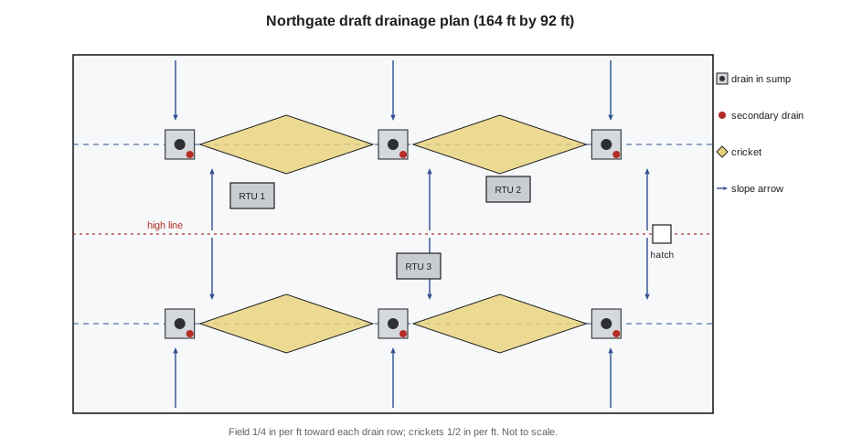
Four drains for 15,088 ft² meant long flow paths and thick taper, and one of them was in the wrong place. Martin's draft has six primary drains in two rows running east to west, about 23 ft in from the north and south edges, with three drains in each row about 55 ft apart. Two of the existing drains are kept and reset in new sumps, two are moved a short way to the new rows, and two new drains are added, one of them at the bottom of the sagging bay. The mechanical engineer routed the two new leaders down beside columns, clear of the laboratory.
Worked problem
Flow per drain
At the sample design intensity of 2.9 in/h, what flow does each of the six drains carry, and how does that compare with the old four-drain layout?
Show solution
- Total = 0.0104 × 2.9 × 15,088 = 455 gal/min.
- Six drains: 455 ÷ 6 = 76 gal/min each. Four drains: 455 ÷ 4 = 114 gal/min each.
Answer: Each drain carries a third less water, and no point on the roof is more than about 27 ft from a drain in plan.
Step 3: the slope
With the drain rows set, the field slope runs north and south from the edges and from the center line of the roof down to each row at 1/4 in per foot. Between the drains in each row, diamond-shaped crickets sloped at 1/2 in per foot, twice the field slope, carry water along the drain line to the drains. Martin made them about 15 ft wide, close to a third of their length, as the rule of thumb in lesson 3 suggests. Near the east and west edges, the taper turns so those strips slope toward the end drains. The maker's design service drew the panel layout from Martin's sketch and the survey.
Worked problem
Taper thickness along the longest path
The longest field path, from the north edge to the north row of drains, is 23 ft. With taper starting at 1/2 in at the drain line and rising at 1/4 in per foot, how thick is the taper at the edge?
Show solution
- Rise = 23 × 1/4 = 5-3/4 in.
- Taper at the edge = 1/2 + 5-3/4 = 6-1/4 in.
Answer: 6-1/4 in of taper along the north and south edges. At the four corners, where the slope also turns toward the end drains, the taper reaches about 7-1/4 in.
Step 4: the assembly
Martin's roof type for Northgate, from the bottom up:
| Layer | Product | Attachment |
|---|---|---|
| Steel deck | Existing; corroded sections replaced | — |
| Air and vapor barrier | Self-adhered, on primed deck, product rated to span the flutes | Self-adhered; sealed to wall air barrier at edges |
| Base insulation | Two layers of 2 in polyiso, joints staggered | Fastened together with screws and plates, 5 in fasteners |
| Tapered insulation | Polyiso panels, 1/4 in per foot field, 1/2 in per foot crickets, sumps at drains | Low-rise foam adhesive |
| Cover board | 1/2 in glass-mat gypsum, primed | Low-rise foam adhesive |
| Membrane | 60 mil TPO, white | Fully adhered |
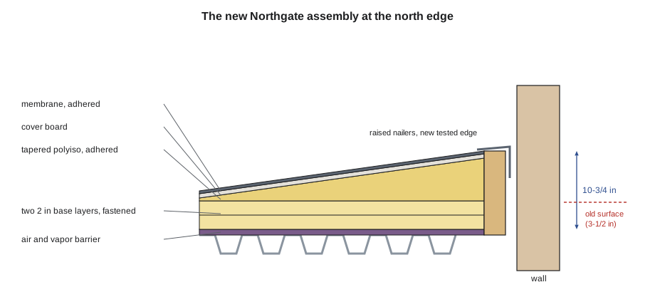
Every layer answers one of the spring findings. The barrier and the staggered layers stop the air that soaked the old insulation (lessons 5 and 6). Fastening only the base layers and adhering everything above keeps the fasteners buried and the membrane unpierced (lesson 4). The cover board protects the polyiso on the routes to the rooftop units. And the whole stack is one of the membrane maker's assemblies with an FM Approvals rating for the uplift the building needs, with heavier attachment in the perimeter and corners.
Step 5: checking the numbers
Worked problem
Energy and condensation checks
Average polyiso = 4 + (1/2 + 6-1/4) ÷ 2 = 7.375 in in the field (the maker's calculation, which includes the crickets and corners, came out slightly higher). At Martin's design value of R-5.0 per inch, does the roof meet the IECC's R-30? Treating the field as a uniform slope from 4.5 in to 10.25 in of polyiso and averaging the U-factors properly gives an assembly U of about 0.0276. Does that meet U-0.032? And is the barrier at the thinnest point warm enough?
Show solution
- Average R = 7.375 × 5.0 = R-36.9, which is more than R-30.
- Assembly U = 0.0276, which is less than 0.032.
- Barrier at the thinnest point: 68 °F on a 0 °F night (lesson 6), far above the 45 °F dew point.
Answer: The roof passes on average insulation, on assembly U-value calculated the correct way, and on condensation at the barrier. Using a cold-weather design value for the polyiso gives a margin for January.
Step 6: the heights
Rory had been waiting for this part, because Dana had told him it was where designs fall apart. Every curb, hatch, drain and edge on the roof had to be checked against the new surface. Martin's rule, following the membrane maker, was at least 8 in of flashing height above the finished roof at curbs and walls.
Worked problem
The north edge and the curbs
Along the north edge, the new build-up is 4 in of base, 6-1/4 in of taper and 1/2 in of cover board. The old build-up was 3-1/2 in. How much higher is the new surface at the edge? Rooftop unit 3's curb stands 14 in above the old surface, at a spot where the new surface rises 6 in. How much curb is left?
Show solution
- New build-up = 4 + 6-1/4 + 1/2 = 10-3/4 in. Rise = 10-3/4 − 3-1/2 = 7-1/4 in.
- Curb left = 14 − 6 = 8 in, exactly the minimum.
Answer: The edge rises 7-1/4 in, so new wood nailers are built up to the new height under a new tested edge system with a continuous cleat, fixing the spring's finding 2. Rooftop unit 3's curb would be at the bare minimum, and the other two are lower, so Martin specified curb extensions for all three units and for the roof hatch.
Glen added a note for the estimate: curb extensions mean the mechanical contractor must disconnect and lift each unit, so the roof work around each curb has to be scheduled with them, on a weekend if possible so the clinics keep their heating and cooling during the week.
Step 7: secondary drainage
With the edges raised 7-1/4 in above the drain lines, the roof can now hold water like a shallow tray if the drains block. Northgate has no parapets, but its raised perimeter traps water in the same way. Martin added a secondary overflow drain beside each primary drain, with its inlet 2 in above the primary, piped separately and discharging through nozzles on the north and south walls where clinic staff will see any flow (lesson 8). The structural engineer checked the roof for the deepest water that could build up at the drains before the overflows ran, about 3-1/2 in including the head.
Worked problem
The water load at the drains
What load does 3-1/2 in of water put on the roof at the drains?
Show solution
- 3.5 × 5.2 = 18.2 psf.
Answer: About 18 psf near the drains, falling to nothing up the slope. The engineer accepted it once the rooftop unit bay was reinforced.
Step 8: quantities for the budget
Rory's job for the last hour was a first takeoff for Glen's budget, using the plan, the roof type and the fastener pattern from lesson 4:
| Item | Quantity before waste | How it was found |
|---|---|---|
| Air and vapor barrier | 15,088 ft² plus edge turn-ups | Roof area plus about 2 ft at each edge |
| Base polyiso, 2 layers of 2 in | 30,176 ft², about 943 boards of 4 × 8 ft | 2 × 15,088 ÷ 32 |
| Base fasteners and plates | about 4,300 | Lesson 4 pattern by zone |
| Tapered polyiso | about 50,900 board feet in the field, plus crickets and sumps | 15,088 × 3.375 in average taper |
| Cover board, 1/2 in | 15,088 ft², about 472 boards | 15,088 ÷ 32 |
| Drains | 6 primary, 6 secondary | Martin's plan |
Glen checked each line, added waste factors, and replaced Rory's tapered estimate with the quantities from the maker's layout once it arrived. "Your number was close," he said. "Close is what a budget needs. A bid needs the panel count."
Step 9: what the review changed
Ridgecap's review sent Martin four comments:
- Show the air barrier connection to the wall at every edge in a detail, because the 2014 walls have their air barrier behind the brick and the transition will be hard to reach; consider a sheet-metal and membrane transition from the top of the wall.
- Add crickets on the uphill side of all three rooftop units and the roof hatch, not just unit 3.
- Specify the cold-weather grade of adhesive and an allowance for heating the containers, in case the work runs into October.
- Phase the tear-off over the dental suite and laboratory for weekends and keep a temporary roof ready, because the barrier there must go down the same day the old roof comes off.
Martin accepted all four. The drawings are to be issued for the owner's budget in December, and for tender in early 2028; the work is planned for the summer of 2028.
What the case shows
At the end of the morning, Glen asked Rory to say in one sentence what Northgate had taught him. Rory took a while. "That a roof is designed from the bottom up and the outside in," he said. "The deck and the drains decide the slope, the air barrier decides whether the insulation stays dry, the code decides how thick it is, and the thickness decides every curb and edge on the roof." Glen wrote it on the top of Martin's drawing sheet in pencil. "Put that on your trade school exam," he said.
Common mistakes
MistakeDesigning taper without surveying the real deck.
InsteadSurvey elevations and drains first, as at Northgate.
MistakeAdding insulation without checking curbs, hatches and edges.
InsteadCheck every height against the minimum flashing height before ordering.
MistakeRaising a roof's perimeter without secondary drainage.
InsteadProvide overflow drains or scuppers and have the structure checked for the trapped water.
MistakeAveraging R-values to show energy compliance on a tapered roof.
InsteadAverage U-values and check the thinnest point.
MistakeLeaving the air barrier connection at the walls to be worked out on site.
InsteadDetail it on the drawings and build it as drawn.
Summary and key terms
- Northgate's re-roof design follows from its failures: missing air barrier, single insulation layer, poor corners and edges, and ponding.
- The structure is checked first; the sagging bay is reinforced and the added weight confirmed.
- Six drains in two rows, a 1 in 50 field and crickets at twice that slope shorten every flow path.
- The assembly uses a sealed barrier on the deck, fastened base layers, adhered taper and cover board and an adhered membrane.
- Energy, assembly U-value and condensation checks all pass with conservative values.
- Raising the roof raises every curb and edge and calls for secondary drainage; the contractor's review improves buildability.
- Design goal
- A plain statement of what a design must achieve, used to judge each decision.
- Constructability review
- A contractor's review of a design to find what will be hard or costly to build.
- Curb extension
- A section added to the top of an existing curb to raise it above a thicker new roof.
- Takeoff
- A list of quantities measured from drawings for an estimate or order.
- Phasing
- Dividing work into stages to suit occupants, weather or other trades.
- Secondary overflow drain
- A drain beside a primary drain, with a raised inlet and its own piping.
- Tested edge system
- Edge metal that has passed a wind test for the building's design pressure.
- Budget estimate
- An early cost estimate used by an owner to plan funding.
Practice problems
Work each problem on paper first, then reveal the answer to check.
Why did Martin add two drains rather than just thicker taper?
Show answer
Shorter flow paths mean less taper and lower edges, and the sag needed a drain at its low point.
The field slope is 1/4 in per foot. What slope did Martin give the crickets?
Show answer
1/2 in per foot, twice the field slope.
New build-up at an edge is 10-3/4 in and the old was 3-1/2 in. How much does the edge rise?
Show answer
7-1/4 in.
Why are secondary drains needed at Northgate even without parapets?
Show answer
The raised perimeter can trap water if the drains block.
Name one item Ridgecap's review added.
Show answer
Crickets at all curbs, the air barrier edge detail, cold-weather adhesive, or weekend phasing over the clinics.
Lesson quiz · 5 questions
Score 60% or more to complete this lesson.
Create a free account to save your progress, take quizzes and earn a certificate.