
ROOF-220 · Lesson 10 of 12 · 25 min
Single-ply flashings and details
▶ Video coming soon A video version of this lesson is on the way.
On Wednesday, October 21, Sabine put Rory on the details at the warehouse. The field sheets were nearly all down and welded, and what remained was the slow, careful work around the edges: 720 ft of parapet on the north, east and west sides, the coated-metal edge along the loading docks on the south, seven rooftop unit curbs, eight skylight curbs, six drains and twenty-two pipes and vents. "The field took four weeks," Sabine said. "The details will take three. And that's where every leak you'll ever chase lives."
This lesson covers flashings and details on single-ply roofs: the rules that apply to every flashing, then parapets and walls, curbs, corners, pipes, drains, roof edges and the protection of the finished roof.
The rules for every flashing
- Secure the field membrane first. At the base of every wall, curb and angle change, the field membrane is fastened or bonded so it cannot pull on the flashing (lesson 5). The flashing is then lapped onto the field membrane and welded or taped.
- Height. Base flashings rise at least 8 in above the finished roof surface, the common minimum in maker details and NRCA guidance, and higher where snow or ponding is expected.
- Adhered, not loose. Flashing membrane is fully adhered to the wall or curb with bonding adhesive, or mechanically fastened at intervals the maker sets, so wind cannot flutter it.
- Terminated. Where flashing stops below the top of a wall, it ends under a termination bar, fastened at close spacing and sealed, and is covered by a counterflashing or wall cladding. Where it goes over the top of a parapet, it ends under the coping.
- Use the maker's accessories: pre-molded corners and pipe boots, unreinforced flashing, coated metal and sealants made for the system.
- Shed water. Laps face downhill, and nothing relies on sealant alone to keep water out.
"Sealant is a maintenance item," Sabine said. "If your detail only works while the caulking is fresh, it's not a detail."
Parapets and walls
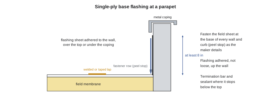
At Alum Creek the parapets were 18 in high, concrete block with a wood nailer on top. The detail:
- Fasten the field membrane at the base of the parapet with a row of plates and screws, or a fastening bar, within the maker's distance of the wall.
- Cut flashing strips from the membrane roll, wide enough to go up the wall, over the top of the nailer and down the outside a short way, plus a lap onto the field.
- Apply bonding adhesive to the wall and the back of the flashing (an adhesive approved for TPO), let it flash off, and set the flashing into the angle without bridging, then up the wall and over the nailer. Press and roll it.
- Weld the bottom edge of the flashing to the field membrane, with the lap covering the base fasteners.
- Fasten the flashing on top of the nailer as the maker shows, then install the metal coping over it.
On the hall at St. Brendan's, the north side met the stone wall of the church. There, the EPDM wall flashing ran up 12 in and ended under a termination bar screwed into the stone at close spacing and sealed with the maker's sealant, and the church's existing copper counterflashing, reset in the stone joint above, came down over it.
Worked problem
Flashing membrane for the parapets
Alum Creek's parapets total 720 ft. The flashing goes up 18 in, across the 10 in parapet top, and laps 6 in onto the field, so each strip must be 34 in wide. Strips are cut three to a 10 ft roll, each 100 ft long. How many rolls are needed?
Show solution
- Strip width check: 3 × 34 = 102 in, which fits in 120 in, leaving 6 in per strip for trimming and laps.
- Strips needed = 720 ÷ 100 = 7.2, so 8 strips.
- Rolls = 8 ÷ 3 = 2.7, so 3 rolls.
Answer: Three rolls of flashing membrane, plus the end laps between strips and the corners, which use unreinforced flashing and pre-molded pieces.
Corners
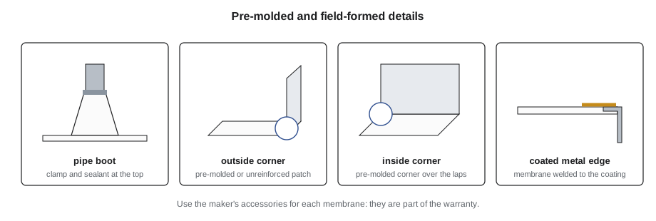
Corners are where three planes meet and where membrane must stretch or be cut. Inside corners, where two walls meet the roof, and outside corners, at the corners of curbs, get either a pre-molded corner from the maker or a piece of unreinforced flashing, which can be stretched with heat into the shape, welded over the cut flashing laps. Reinforced membrane is never stretched around a corner: the scrim does not stretch, and the membrane over it thins and splits, as it had at Corso's.
Owen taught Rory the order for an outside curb corner: flash both faces of the curb with reinforced membrane, cut the corner so the pieces lie flat with a small overlap, weld those laps, then weld a pre-molded outside corner over the whole intersection, its skirt lapping onto the field, and finally probe all the welds once cool. Rory did six corners on Wednesday. Owen made him cut out the second one and do it again.
Curbs
Rooftop units, exhaust fans, skylights and hatches sit on curbs, raised frames that lift them above the roof surface so they can be flashed. A curb must be tall enough that the flashing meets its minimum height above the finished roof, including any added insulation on a re-roof. At Alum Creek, three old rooftop unit curbs were too low once the new 6 in of insulation was added, and the mechanical contractor raised them with curb adapters before the roof went on.
- Secure the field membrane around the base of the curb.
- Flash each face of the curb with reinforced membrane, adhered, lapping onto the field.
- Weld the vertical laps at the corners and add pre-molded corners.
- Fasten the flashing at the top of the curb and cover it with the unit's flange or a metal counterflashing.
The eight skylights got the same treatment, and their new screens, designed to carry a falling worker, were fastened to the curbs before the crew finished.
Pipes and penetrations
Round pipes and vents are flashed with pre-molded pipe boots: cones of unreinforced membrane in stepped sizes, cut at the step that fits the pipe snugly, slid down the pipe, welded to the field membrane all round at the base, and clamped and sealed at the top with a stainless steel clamp. Where a pipe is too big, too hot or oddly placed for a boot, the maker's field-formed detail is used, built from unreinforced flashing.
Some penetrations cannot be flashed at all, such as clusters of conduit or angle-iron supports. These are moved, sleeved or set in a sealant pocket (sometimes called a pitch pocket), a pre-made collar filled with the maker's pourable sealer. Sealant pockets need regular maintenance and are a last resort.
Hot pipes, such as some boiler and generator exhausts, need the clearance and insulation the maker specifies, because hot metal can soften or scorch a thermoplastic membrane.
Worked problem
Choosing pipe boots
Pipe boots in this system come in two sizes: small for pipes 1 to 4 in in diameter and large for 4 to 8 in. Alum Creek has 22 penetrations: 9 plumbing vents of 3 in, 6 of 4 in, 4 gas pipes of 2 in and 3 conduits of 6 in. How many of each boot, if a 4 in pipe uses a small boot cut at its largest step?
Show solution
- Small boots: 9 + 6 + 4 = 19.
- Large boots: 3.
- Total 22, plus spares.
Answer: Nineteen small and three large. Owen ordered two spares of each, because a boot cut at the wrong step cannot be uncut. The gas pipes were also checked for the support blocks and clearances the gas code requires before flashing.
Drains
Roof drains are the low points the whole roof is built to feed. At each drain:
- The insulation is tapered down into a sump around the drain so water reaches it (ROOF-310).
- The field membrane runs over the drain bowl, is cut to the inside diameter of the clamping ring, and is set in a bead of the maker's sealant (water cut-off mastic) on the drain flange.
- The clamping ring is bolted down evenly, so the membrane is squeezed tight between ring and flange all round.
- The strainer dome is replaced.
Membrane seams are kept out of the drain sump where possible, because a seam that holds standing water all its life is a seam that will be tested hard. At Alum Creek, two old drain bowls were cracked and were replaced by the plumber before the roof went over them.
Roof edges
On the south side of Alum Creek, over the loading docks, there was no parapet. The roof edge was finished with a metal edge, called a gravel stop or fascia, made from TPO-coated steel:
- A wood nailer at the edge, securely fastened to the structure, gives the edge metal something to hold.
- The field membrane runs over the nailer to the outside edge and is fastened there.
- The coated metal edge is set over the membrane and nailed to the nailer at close spacing, with a continuous cleat on the outside face for the bottom edge where the design requires.
- The joints between metal pieces are left with a small gap for expansion and covered with a strip of unreinforced membrane welded over the joint.
- A strip of membrane is welded from the field onto the coated flange, sealing the edge.
Edge metal holds down the edge of the roof, where wind uplift starts. The International Building Code requires edge securement on low-slope membrane roofs (other than gutters) to be designed and installed to ANSI/SPRI/FM 4435/ES-1, so the edge metal used is a system tested to that standard. Shop-made edges must match the tested design.
Worked problem
Coated metal edge for the loading docks
The south edge is 320 ft long. Coated metal edge comes in 10 ft pieces, installed with 1/4 in gaps between them. How many pieces are needed, and how many joint covers?
Show solution
- Each piece plus gap covers 10 ft 1/4 in = 10.021 ft.
- Pieces = 320 ÷ 10.021 = 31.93, so 32 pieces, with the last one cut.
- Joints between 32 pieces = 31 joint covers.
Answer: Thirty-two pieces and thirty-one joint covers, plus the two corner pieces where the edge meets the east and west parapets.
Other details
- Expansion joints, where the building is designed to move, need flexible joint covers detailed by the designer (ROOF-320).
- Equipment supports and pipe supports sit on pads of membrane or approved blocks, not directly on the roof, and are not fastened through the membrane unless flashed.
- Lightning protection, solar racking and antennas each need maker-approved attachment details.
- Transitions between different roofs, such as TPO meeting an existing mod-bit roof, use the makers' approved transition details.
Order of work around a curb
Owen gave Rory a sequence for every curb on the roof, written on the back of a test weld sheet:
- Check the curb height and condition; report anything too low, loose or rotten before flashing it.
- Fasten the field membrane around the curb base, within the maker's distance of the curb.
- Clean the curb faces and the field membrane where the flashing will lap; let the cleaner dry.
- Measure and cut the four flashing pieces, long enough to lap past each corner, wide enough to reach the top of the curb plus the lap onto the field.
- Adhere each piece to its face, pressing it into the angle without bridging.
- Weld the bottom laps to the field, then the vertical corner laps.
- Weld pre-molded corners over all four corners.
- Fasten the flashing at the top of the curb and install the counterflashing or unit flange.
- Probe every weld once cool and record the curb as done on the roof plan.
"Same order every time," Owen said. "Then when you're tired at three o'clock, your hands still know what comes next."
Walkways and protection
The last details at Alum Creek were the walkway pads: routes from the roof hatch to every rooftop unit and around the skylights, so the technicians who service the units would walk on pads, not on the membrane. The pads, thick textured TPO, were welded along their edges with gaps between them for drainage. Owen also had the crew weld a sacrificial layer of membrane under the service doors of each rooftop unit, where technicians kneel and drop tools.
Common mistakes
MistakeStretching reinforced membrane around a corner.
InsteadUse pre-molded corners or heat-formed unreinforced flashing over cut, welded laps.
MistakeLeaving flashing loose up a wall.
InsteadAdhere it fully or fasten it at the maker's spacing.
MistakeRelying on sealant to keep water out of a detail.
InsteadBuild details that shed water with laps; sealant is a secondary seal.
MistakeSkipping base securement at walls and curbs.
InsteadFasten the field membrane at every angle change before flashing.
MistakeUsing shop-made edge metal that does not match the tested edge system.
InsteadInstall edge metal tested to the required standard, as designed.
Summary and key terms
- Secure the field membrane at every angle change, then lap the flashing onto it.
- Base flashings rise at least 8 in, adhered, terminated under a bar, counterflashing or coping.
- Corners use pre-molded or unreinforced pieces; reinforced membrane is never stretched.
- Curbs must be high enough after new insulation; pipes get boots, odd penetrations get field details or, as a last resort, sealant pockets.
- Drains: membrane set in sealant and clamped evenly under the ring; seams kept out of sumps.
- Edge metal is a tested, fastened system; walkway pads protect traffic routes.
- Base flashing
- Membrane that runs from the roof up a wall or curb, lapped onto the field membrane.
- Termination bar
- A metal or plastic bar fastened along the top edge of a flashing to hold and seal it.
- Counterflashing
- Metal or cladding that covers the top of a base flashing.
- Pre-molded corner
- A factory-formed corner piece of unreinforced membrane.
- Pipe boot
- A pre-molded stepped cone of membrane for flashing a round pipe.
- Sealant pocket
- A collar filled with pourable sealer around a penetration that cannot be flashed otherwise.
- Coated metal
- Sheet metal with a factory TPO or PVC coating, bent into edges and flashings that membrane welds to.
Practice problems
Work each problem on paper first, then reveal the answer to check.
What is the common minimum base flashing height?
Show answer
8 in above the finished roof surface.
Why is reinforced membrane not stretched around an outside corner?
Show answer
The scrim does not stretch, so the membrane thins and splits.
Parapets total 500 ft; strips 100 ft long, three per roll. How many rolls?
Show answer
5 strips; 5 ÷ 3 = 1.7, so 2 rolls.
What is a sealant pocket, and why is it a last resort?
Show answer
A collar filled with pourable sealer around a hard-to-flash penetration; it needs regular maintenance.
Why must curb heights be checked on a re-roof?
Show answer
Added insulation can leave the flashing below its minimum height.
Lesson quiz · 5 questions
Score 60% or more to complete this lesson.
Create a free account to save your progress, take quizzes and earn a certificate.