
RCDD-160 · Lesson 4 of 12 · 32 min
Calculation practice: fill, loss budgets and sizing
▶ Video coming soon A video version of this lesson is on the way.
Calculation items are the ones Daniel fears and the ones Roz thinks he should welcome. A calculation item has one right answer, the method can be practiced until it is automatic, and the distractors are usually the results of predictable mistakes: a forgotten term, a wrong unit, a rounding step in the wrong direction. A candidate who drills the common methods can turn those items into reliable marks. This lesson collects the calculations that appear across RCDD design work and gives a method, a worked example and the usual traps for each. The numbers used are typical values for practice; on the exam and in design, use the values in the current standards and the reference material.
Roz's drill format is the same for every method: write the formula or rule from memory, set out the given values with units, compute step by step, check the result for reasonableness, and state the answer with its unit. The check step catches most errors. A loss budget of 24 dB for a short campus link, a conduit that holds 300 cables or a rack that needs a cooling unit the size of a car are signs of a slip, not answers.
Conduit and pathway fill
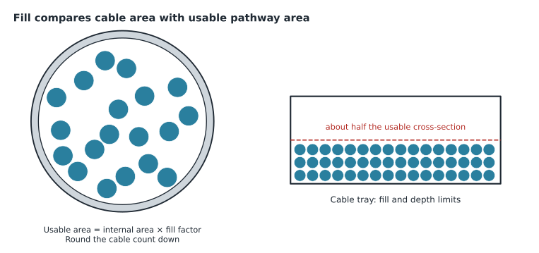
Fill calculations compare the total cross-sectional area of the cables with the usable area of the pathway. For a single cable in a conduit, the area of a cable of diameter d is π times d squared over four. For a group of cables, add the areas. The usable area is the internal area of the conduit multiplied by a fill factor. A design fill of about four tenths (0.40) of the internal area is commonly used for three or more cables in communications conduit, and many owners specify less to leave room for growth; check the factor in the governing standard and the owner's requirements.
Here N is the number of cables, k is the fill factor, A is the internal area of the conduit and d is the cable diameter. Always round N down; a fraction of a cable cannot be installed. Bends reduce how much cable can be pulled through a conduit section, and pathway standards limit the number and total angle of bends between pull points and the length of each section. The usual design rule is no more than two 90 degree bends, or 180 degrees in total, between pull points, and a section length of no more than about 30 meters. Confirm both in the current standard.
Worked problem
Cables in a conduit
A conduit has an internal diameter of 52.9 mm, as for a common 2 inch trade size. Category 6A cables are 7.5 mm in diameter. Using a fill factor of 0.40, how many cables fit?
Show solution
- Internal area: π × (52.9 / 2)² = π × 699.6 = 2198 mm².
- Usable area: 0.40 × 2198 = 879 mm².
- Cable area: π × (7.5 / 2)² = π × 14.06 = 44.2 mm².
- N = 879 / 44.2 = 19.9.
- Round down: 19 cables.
Answer: 19 cables. Rounding up to 20 is the most common error; the distractor is usually 20.
Cable tray fill is calculated the same way, using the tray's usable cross-section. A common design limit is that cable fill should not exceed half of the usable cross-section, and cables should not be stacked deeper than about 150 mm; check both in the pathway standard and the manufacturer's data. Tray load is a separate check: the weight of the cable per meter must not exceed the tray's rated load for the span between supports.
Horizontal lengths and work area cords
Horizontal length items test the 90 meter permanent link and the 100 meter channel, measured as installed, including slack and vertical runs, not as a straight line on the plan. Add the routed length, the drops to the outlet and the service loop in the room. Where a multi-user telecommunications outlet assembly serves an open office, the work area cord may be longer than usual if the horizontal cable is shorter, using the formula from the cabling standard.
Here H is the horizontal cable length, D a de-rating factor for the cord's construction, commonly 0.2 for 24 AWG cords and 0.5 for 26 AWG cords, C the combined length of work area cord, equipment cord and patch cord, T the length of the cords in the telecommunications room, and W the maximum work area cord. The standard also caps the work area cord length; check the cap in the current edition.
Worked problem
A MUTOA cord length
A MUTOA is fed by 70 m of horizontal cable. Cords are 24 AWG, so D = 0.2, and the room cords total 5 m. What is the maximum work area cord?
Show solution
- C = (102 − 70) / (1 + 0.2) = 32 / 1.2 = 26.7 m.
- W = 26.7 − 5 = 21.7 m.
- Check the work area cord cap in the current standard; if it is lower, the cap governs.
Answer: About 21.7 m by the formula, limited by the standard's cap if that is lower.
Optical loss budgets
An optical loss budget adds up the expected loss of a link: cable attenuation, connector pairs and splices. The total is compared with the loss the application allows, and with a test limit. The method is the same for multimode and singlemode; only the values change.
Here α is the cable attenuation in decibels per kilometer at the test wavelength, L the length in kilometers, n_c the number of mated connector pairs, a_c the allowance per pair, n_s the number of splices and a_s the allowance per splice. Typical maximum values for practice are 3.5 dB per km for multimode at 850 nm, 1.0 dB per km for indoor singlemode, 0.5 dB per km for outside plant singlemode, 0.75 dB per connector pair and 0.3 dB per splice. Two traps account for most errors: counting connectors instead of mated pairs, and forgetting to convert meters to kilometers.
Worked problem
A campus link budget
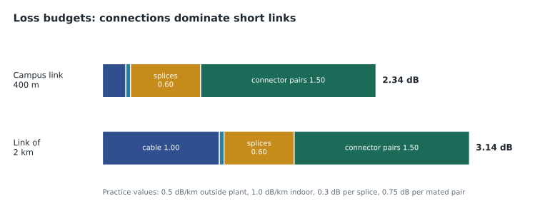
The Harborview campus link is 400 m of outside plant singlemode spliced at each end to 25 m and 15 m of indoor cable, with a connector pair at each patch panel. Using the practice values, what is the budget at 1310 nm?
Show solution
- Outside plant cable: 0.400 km × 0.5 = 0.20 dB.
- Indoor cable: 0.040 km × 1.0 = 0.04 dB.
- Splices: 2 × 0.3 = 0.60 dB.
- Connector pairs: 2 × 0.75 = 1.50 dB.
- Total: 0.20 + 0.04 + 0.60 + 1.50 = 2.34 dB.
Answer: 2.34 dB. Connectors and splices dominate short links; cable attenuation dominates long ones.
Decibels and power
Decibel arithmetic underlies loss budgets, wireless link budgets and amplifier gains. A ratio in decibels is ten times the base-ten logarithm of a power ratio. Three decibels is about a doubling or halving of power, ten decibels a factor of ten. Power in dBm is decibels relative to one milliwatt, so 0 dBm is 1 mW, 10 dBm is 10 mW, 20 dBm is 100 mW and 30 dBm is 1 W. Gains and losses in decibels are added and subtracted, which is why budgets are kept in decibels.
Free-space path loss for a radio link, with distance d in meters and frequency f in megahertz, is twenty times the logarithm of d plus twenty times the logarithm of f, minus 27.55. It grows by six decibels each time the distance doubles. Effective isotropic radiated power is the transmitter power plus the antenna gain minus the cable and connector losses.
Worked problem
A wireless link budget
An access point transmits at 17 dBm through a cable and connectors with 2 dB of loss into an antenna with 5 dBi of gain. What is the EIRP in dBm and in milliwatts?
Show solution
- EIRP = 17 − 2 + 5 = 20 dBm.
- 20 dBm = 10^(20/10) mW = 100 mW.
Answer: 20 dBm, or 100 mW.
Bonding conductor sizing
The telecommunications bonding backbone conductor is sized from its length, using the table in the bonding standard. A widely quoted rule of thumb approximates that table as about 2 kcmil of conductor area for each linear foot of conductor, with a minimum of 6 AWG and a maximum of 750 kcmil. Use the rule to check your answer and the table in the current standard for the design. The telecommunications bonding conductor that joins the primary busbar to the building's electrical grounding system must be at least as large as the largest backbone conductor.
| Size | Area (kcmil) |
|---|---|
| 1/0 AWG | 105.6 |
| 2/0 AWG | 133.1 |
| 3/0 AWG | 167.8 |
| 4/0 AWG | 211.6 |
| 250 kcmil | 250 |
| 350 kcmil | 350 |
| 500 kcmil | 500 |
| 750 kcmil | 750 |
Worked problem
Sizing a bonding backbone
The Harborview bonding backbone runs 102 ft from the primary busbar to the rooftop secondary busbar. Use the rule of thumb to estimate the size.
Show solution
- Required area ≈ 2 kcmil × 102 = 204 kcmil.
- 3/0 AWG is 167.8 kcmil: too small.
- 4/0 AWG is 211.6 kcmil: large enough.
- Check against the standard's table, which the design uses.
Answer: 4/0 AWG, which matches the size used in the project design.
PoE and power
Power over Ethernet calculations ask how much power reaches a device, how much is lost in the cabling and how much power and cooling the telecommunications room needs. The IEEE types give, in round numbers, 15.4 W at the source for Type 1, 30 W for Type 2, 60 W for Type 3 and about 90 W for Type 4, with less available at the device because of cable losses. The difference is heat, in the cable bundle and in the room. A switch's power supply must deliver the PoE budget plus the switch's own consumption.
Room load in watts converts to cooling in British thermal units per hour by multiplying by about 3.412, and to tons of refrigeration by dividing the British thermal units per hour by 12,000. One ton is about 3.517 kW. Cooling items often give the load in watts and ask for one of the other units, or the reverse.
Worked problem
Power and cooling for a room
A telecommunications room has four PoE switches. Each draws 220 W for its own electronics and delivers 740 W of PoE to devices on the floor. What electrical load must the room's circuits supply, and how much heat must its cooling remove, if power delivered to devices is treated as leaving the room?
Show solution
- Electrical load: 4 × (220 + 740) = 3840 W.
- PoE power delivered to devices is dissipated at the devices and along the cables, not in the room.
- Heat in the room: the switch electronics, 4 × 220 = 880 W.
- Cooling: 880 W × 3.412 = 3003 BTU/h.
- In tons: 3003 / 12,000 = 0.25 tons.
Answer: 3840 W of electrical load but only about 880 W, or about 3000 BTU/h, of heat in the room. The trap is treating all PoE power as room heat; in a real design, add power supply losses from the manufacturer's data.
Rack and data center sizing
Rack power density drives cooling and power design in data centers. Total IT load divided by the number of racks gives average density; a few dense racks can need special cooling even when the average is modest. Uninterruptible power supply capacity is sized from the load with a margin, and battery runtime depends on the load, the battery capacity and its efficiency. Items usually give the values needed and test the method and the units.
Worked problem
Average rack density
A small data room has 6 racks with a measured total IT load of 21 kW. What is the average density, and what cooling in tons is needed if all of it becomes heat?
Show solution
- Average density: 21 / 6 = 3.5 kW per rack.
- Heat: 21 kW × 3412 = 71,652 BTU/h.
- Tons: 71,652 / 12,000 = 5.97 tons, or 21 / 3.517 = 5.97 tons.
Answer: 3.5 kW per rack and about 6 tons of cooling.
Common mistakes
MistakeRounding a cable count up.
InsteadRound down; a fraction of a cable cannot be installed.
MistakeCounting connectors instead of mated connector pairs.
InsteadA patch panel connection is one mated pair.
MistakeUsing meters where the formula expects kilometers.
InsteadConvert before multiplying by attenuation per kilometer.
MistakeAdding decibels and milliwatts together.
InsteadKeep a budget in one unit; convert at the end.
MistakeTreating all PoE power as heat in the room.
InsteadPower delivered to devices is dissipated where the devices are.
MistakeSkipping the reasonableness check.
InsteadAsk whether the answer could be true before choosing it.
Summary and key terms
- Drill each method: rule from memory, givens with units, steps, check, answer with unit.
- Fill: usable area is internal area times fill factor; round cable counts down.
- Loss budget: attenuation times length plus mated pairs and splices times their allowances.
- Decibels: 3 dB is about double, 10 dB is ten times; dBm is relative to 1 mW.
- Bonding backbone: about 2 kcmil per linear foot as a check, sized from the standard's table.
- PoE and power: switch load includes PoE; room heat excludes power delivered to devices.
- Cooling: watts × 3.412 = BTU/h; BTU/h ÷ 12,000 = tons.
- Fill factor
- The share of a pathway's internal area that cables may occupy.
- Loss budget
- The sum of expected losses in an optical link.
- Mated connector pair
- Two connectors joined at an adapter; the unit of connector loss.
- dBm
- Power in decibels relative to one milliwatt.
- EIRP
- Effective isotropic radiated power: transmitter power plus antenna gain minus losses.
- kcmil
- Thousand circular mils, a unit of conductor area.
Practice problems
Work each problem on paper first, then reveal the answer to check.
A conduit's usable area is 879 mm² and each cable occupies 44.2 mm². How many cables?
Show answer
19, rounded down from 19.9.
A multimode link is 90 m with two connector pairs. What is the budget at 850 nm using the practice values?
Show answer
0.09 × 3.5 + 2 × 0.75 = 0.32 + 1.50 = 1.82 dB.
What is 27 dBm in milliwatts, approximately?
Show answer
About 500 mW.
Estimate the bonding backbone area for 60 ft.
Show answer
About 120 kcmil, so 2/0 AWG as a check.
Convert 5 kW of heat to tons.
Show answer
5 × 3412 / 12,000 ≈ 1.42 tons.
How much does free-space path loss rise when the distance doubles?
Show answer
About 6 dB.
Lesson quiz · 5 questions
Score 60% or more to complete this lesson.
Create a free account to save your progress, take quizzes and earn a certificate.