
RCDD-114 · Lesson 6 of 12 · 20 min
Building automation and intelligent buildings
▶ Video coming soon A video version of this lesson is on the way.
The mechanical engineer on Harbourview sends Daniel a controls riser diagram that looks like a subway map. It shows air handling units on the roof, variable air volume boxes on every floor, chillers and boilers in the penthouse, meters on every electrical panel, occupancy sensors in every room and a supervisory server somewhere called 'BAS head end, location TBD'. Across the bottom, someone has written: 'Controls contractor to provide all network cabling.' Roz reads it over Daniel's shoulder and frowns. 'That last line is how buildings end up with three parallel networks nobody can maintain,' she says. 'Let's find out what the controls actually need and decide which parts belong on our infrastructure.'
Building automation systems, or BAS, monitor and control the mechanical, electrical and other services of a building: heating, ventilation and air conditioning, lighting, shading, metering, elevators and sometimes plumbing and life safety interfaces. They save energy, keep occupants comfortable and alert operators to faults. An intelligent building goes further, combining data from many systems to optimize how the building is used and operated. Both depend on reliable communications between thousands of sensors, controllers and servers. For the RCDD, building automation raises the same question as AV and security did: how much of this communication should ride on the structured cabling system, and what does it need from the infrastructure?
The layers of a building automation system
Most building automation systems have three layers. At the field level, sensors measure temperature, humidity, pressure, flow, carbon dioxide, occupancy and light, and actuators move dampers and valves or switch equipment. These devices connect to controllers that run control sequences for a piece of equipment, such as an air handling unit or a zone. Controllers communicate with each other and with the supervisory level, where servers and operator workstations store data, schedule equipment, raise alarms and present graphics. Older systems used proprietary serial networks at the field and controller levels and an Ethernet network only at the top. Newer systems push IP networking down to the controllers and, increasingly, to field devices themselves.
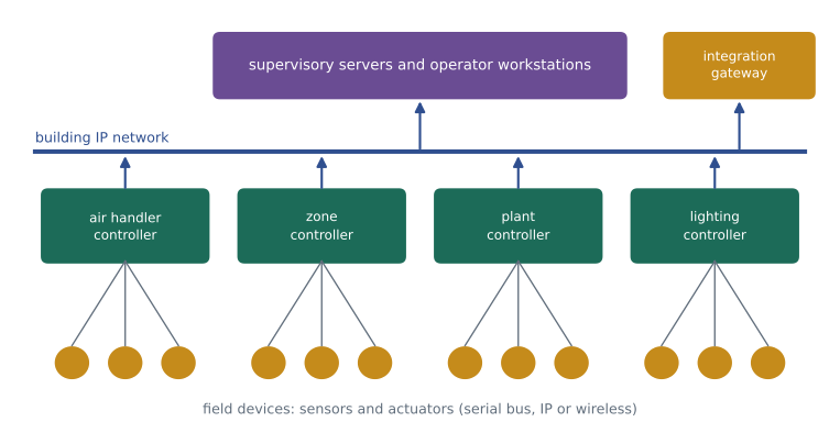
Protocols the RCDD should recognize
Building automation uses several communication protocols. BACnet, standardized as ISO 16484-5 and developed by ASHRAE, is the most widely used open protocol for building automation in North America. It runs over IP networks as BACnet/IP and over a serial bus called BACnet MS/TP that uses twisted-pair cable daisy-chained between controllers. Modbus is common for meters, variable frequency drives and packaged equipment, over serial links or TCP/IP. Lighting systems may use DALI, a digital lighting control protocol, and some systems use KNX, which is more common in Europe. Wireless sensors use protocols such as Zigbee, Bluetooth Low Energy or proprietary radio links.
The RCDD does not need to configure any of these, but should recognize what each implies for cabling. IP-based protocols ride on structured cabling and network switches. Serial protocols such as BACnet MS/TP and Modbus RTU need their own twisted-pair cabling, usually in a bus or daisy-chain arrangement with limits on length and number of devices, and are typically installed by the controls contractor. Wireless sensors need gateways with network connections and sometimes power. Knowing which protocols are planned tells the RCDD which parts of the system will need outlets and switch ports.
| Protocol or technology | Typical use | Physical layer | Infrastructure implication |
|---|---|---|---|
| BACnet/IP | Controllers and supervisory servers | Ethernet over balanced cabling | Outlets and switch ports at controllers; network design |
| BACnet MS/TP | Field-level controllers | Shielded twisted pair in a daisy chain | Controls contractor cabling; pathways only |
| Modbus TCP and RTU | Meters, drives, packaged equipment | Ethernet or serial twisted pair | Ports for TCP devices; pathways for serial runs |
| DALI | Lighting control | Two-wire control bus | Coordinated with lighting design |
| Wireless sensor protocols | Room sensors, retrofit devices | Radio to a gateway | Gateway outlets and power |
Cabling for building automation
TIA-862, the standard for structured cabling for intelligent building systems, describes how to extend the structured cabling system to building automation devices. Its main ideas are a horizontal connection point in the ceiling or floor, which serves a coverage area of the building, and building automation outlets within that area. Instead of running a separate cable from a controller to each device location in an ad hoc way, the designer creates a grid of coverage areas, each served by a connection point fed from the telecommunications room. Devices connect to outlets near the connection point. When devices are added or moved, the cabling already exists nearby.
The approach mirrors the grid outlets used for wireless access points and cameras. It works especially well in open office areas and large spaces where many small devices, such as sensors, occupancy detectors and lighting controls, are spread across the ceiling. It is less suitable for mechanical rooms, where devices are concentrated around equipment and the controls contractor's own wiring is usually more practical. Many projects combine both: structured cabling and grid outlets for IP controllers and ceiling devices on occupied floors, and contractor wiring inside mechanical rooms.
Worked problem
Counting coverage areas
The third floor of Harbourview is 2,700 m² of offices and clinic support space. The owner has adopted a building automation coverage area of 36 m² per area, each with one connection point and allowance for four building automation outlets. How many connection points and outlets should Daniel plan?
Show solution
- Connection points: 2,700 ÷ 36 = 75 coverage areas.
- Outlets: 75 × 4 = 300 building automation outlets.
- Each connection point needs one horizontal cable to the telecommunications room, so 75 horizontal runs.
Answer: About 75 connection points and up to 300 outlets. Not every outlet will be installed on day one; many owners install the connection points and add outlets as devices are placed.
Converged or separate networks
A key decision is whether building automation traffic shares the owner's IP network or runs on its own. A converged approach uses the same switches, backbone and management tools for building systems as for business systems, separated logically by virtual networks and access controls. It reduces duplicated equipment and uses the owner's IT expertise, but it brings building systems under IT change control and security policies that the facilities team may find unfamiliar. A separate approach gives the controls contractor and facilities team their own network, which may be simpler to manage day to day, but duplicates switches and cabling and often ends up less secure because it receives less attention.
Whatever the choice, security matters. Building automation systems have been the entry point for well-known cyberattacks, because they are often connected to the internet for remote monitoring and are rarely patched. Good practice segments building systems from business networks, controls remote access tightly, changes default passwords and keeps an inventory of connected devices. The RCDD contributes by providing clear separation in patch panels and switch ports, secure spaces for building system network equipment and documentation of which outlets serve which systems.
Spaces, power and the head end
Building automation needs space at several levels. Controllers for each floor or zone often sit in mechanical rooms, electrical rooms or the telecommunications room, in enclosures with power and network connections. Supervisory servers need a home in the main equipment room or data room, with backup power so that the building can still be monitored during an outage. Operator workstations sit in a facilities office or a security and operations center. The design should identify each of these locations early, so that the 'location to be determined' on the controls diagram becomes a real room with power, cooling and cabling.
Power also matters at the device level. Many IP controllers and sensors can be powered by PoE, which removes the need for separate low-voltage transformers. Others need 24 V AC or DC from the controls contractor's power supplies. The RCDD should confirm which devices will be PoE-powered and include them in switch budgets and room calculations. Where building automation devices share switches with other systems, a failure in the switch or its power supply affects both, so the reliability needs of the building systems should influence how switches and backup power are arranged.
Worked problem
PoE for building automation
On the third floor, 18 IP controllers will be PoE-powered at up to 13 W each, and 60 PoE occupancy and environmental sensors will draw up to 4 W each. What PoE budget do they need?
Show solution
- Controllers: 18 × 13 = 234 W.
- Sensors: 60 × 4 = 240 W.
- Total: 234 + 240 = 474 W.
Answer: About 474 W of PoE for building automation alone on one floor. Daniel decides to give building systems their own switch in the third-floor telecommunications room so that a failure in the office network cannot shut down room controls.
What makes a building intelligent
An intelligent building collects data from many systems, such as automation, lighting, access control, occupancy sensors, meters and room booking, and combines it to improve how the building operates. Examples include adjusting ventilation to actual occupancy measured by sensors or badge data, turning off lighting and heating in rooms that bookings show are empty, detecting equipment faults before they cause failures, and giving occupants control from their phones. These capabilities depend less on any single system than on integration: common networks, open protocols, consistent naming and data that can be shared securely.
Integration starts with infrastructure. If every system has its own proprietary network, integration requires gateways and custom software. If systems share structured cabling, a common IP network and open protocols, integration is far easier. This is one reason owners increasingly adopt a single converged infrastructure for building systems, with the ICT designer responsible for the cabling, pathways, spaces and network design that all systems share. Lesson 7 looks at that convergence more broadly, and lesson 12 shows how to bring all of the special systems into one design.
Coordinating with the mechanical and controls teams
Building automation design involves the mechanical engineer, the electrical engineer, the controls contractor and often a commissioning agent who tests the system against the owner's requirements. The ICT designer needs from them a list of networked devices with their locations, protocols and power needs, the locations of controllers and servers, and the owner's requirements for network separation and remote access. In return, the ICT design should state clearly which cabling the ICT contractor provides, which the controls contractor provides, where the boundary sits and how the two are tested and documented. Roz's version of the controls riser diagram for Harbourview ends with a different note: 'IP cabling to controllers, sensors and gateways by ICT contractor per ICT drawings; serial bus wiring within mechanical rooms by controls contractor.'
Exam focus: building automation
Exam questions on building automation usually test three ideas. First, recognize which protocols ride on structured cabling, such as BACnet/IP and Modbus TCP, and which need their own serial wiring, such as BACnet MS/TP and Modbus RTU. Second, understand the coverage area approach described in TIA-862, with a horizontal connection point serving the building automation outlets in each area, and be able to count connection points from a floor area and an area size. Third, know why building systems must be segmented and secured, because questions often describe a building automation network exposed to the internet or shared without controls with business systems.
When a question asks who provides building automation cabling, the best answer usually depends on what the design documents say. A well-written design states the boundary clearly, for example IP cabling by the ICT contractor and serial wiring in mechanical rooms by the controls contractor. Answers that leave the boundary undefined are almost always wrong.
Common mistakes
MistakeLetting the controls contractor provide all building automation networking by default.
InsteadDecide deliberately which parts ride on structured cabling and which use contractor wiring, and document the boundary.
MistakeAssuming building automation devices are low-risk for cybersecurity.
InsteadBuilding systems have been the entry point for major attacks. Segment them, control remote access and manage their devices.
MistakeLeaving the BAS head end location undecided.
InsteadSupervisory servers need a real room with power, cooling, backup and network connections.
MistakeForgetting PoE loads from controllers and sensors.
InsteadAdd building automation PoE to switch budgets and room power and cooling.
Summary and key terms
- Building automation monitors and controls HVAC, lighting, metering and other building services through sensors, controllers and supervisory servers.
- BACnet/IP and Modbus TCP ride on structured cabling; serial buses and wireless sensors need contractor wiring or gateways.
- TIA-862 describes coverage areas with connection points and building automation outlets, similar to wireless and camera grids.
- Converged and separate networks each have trade-offs; either way, building systems must be segmented and secured.
- Intelligent buildings depend on integration, which is far easier with shared infrastructure and open protocols.
- Building automation system (BAS)
- A system that monitors and controls building services such as HVAC and lighting.
- BACnet
- An open communication protocol for building automation, standardized as ISO 16484-5.
- MS/TP
- Master-slave/token-passing, a BACnet serial bus over twisted-pair cable.
- Coverage area
- A portion of a floor served by one building automation connection point.
- Horizontal connection point
- A connection point in the ceiling or floor that serves the outlets in a coverage area.
- Intelligent building
- A building that integrates data from many systems to optimize operation and occupant experience.
Practice problems
Work each problem on paper first, then reveal the answer to check.
A 1,800 m² floor uses 36 m² coverage areas. How many connection points?
Show answer
1,800 ÷ 36 = 50.
Name one advantage and one drawback of a converged building systems network.
Show answer
Advantage: less duplicated equipment and stronger management. Drawback: building systems come under IT change control and need clear coordination.
Which BACnet variant needs its own daisy-chained twisted-pair wiring?
Show answer
BACnet MS/TP.
Lesson quiz · 5 questions
Score 60% or more to complete this lesson.
Create a free account to save your progress, take quizzes and earn a certificate.