
RCDD-114 · Lesson 5 of 12 · 20 min
Electronic safety and security systems
▶ Video coming soon A video version of this lesson is on the way.
The clinic on the first floor of Harbourview will store controlled medications, patient records and expensive imaging equipment. The college upstairs will hold exams, laptops and a nursing simulation lab worth more than most houses. Marcus Feld, the general contractor's project manager, forwards an email from the owner's security consultant: forty-two card-controlled doors, ninety cameras, intrusion detection in the pharmacy and the server room, duress buttons in the clinic reception, and an intercom at every public entrance. 'Can your cabling handle this?' Marcus asks. Roz replies with a question of her own. 'Can our cabling be trusted with it? Security systems have to keep working when everything else is under attack.'
Electronic safety and security, often shortened to ESS, covers the systems that protect people and property: access control, video surveillance, intrusion detection, intercoms and emergency call stations, and the monitoring and management systems that tie them together. Fire alarm and life safety systems are related but are usually governed separately by fire codes and installed by specialized contractors; ESS systems may interface with them but rarely share their wiring. Like AV, security has moved from proprietary wiring to IP-based devices on structured cabling and PoE. That convergence brings cost savings and flexibility, but it also brings the security system into the ICT design, with demands for reliability, power and protection that go beyond ordinary data cabling.
Access control
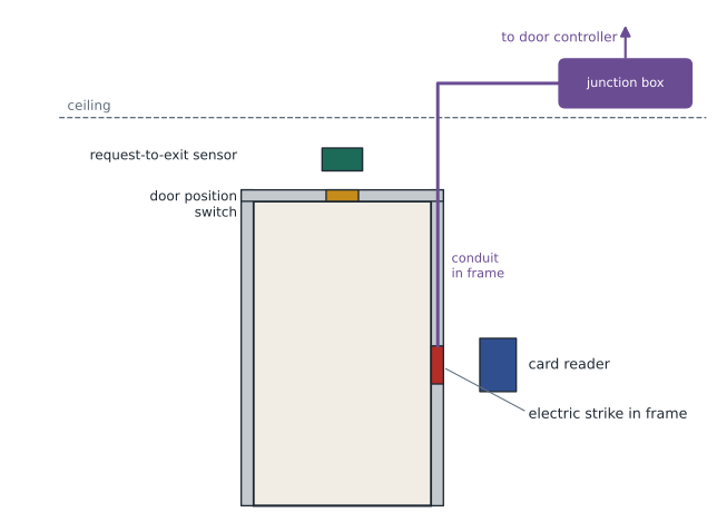
An access control system decides who can pass through which doors at what times. At each controlled door, a reader identifies the credential, a lock or electric strike releases the door, a door position switch reports whether the door is open, and a request-to-exit device lets people leave without setting off an alarm. These devices connect to a door controller, which makes decisions locally and communicates with a central server. Traditional systems use multi-conductor cable from each door to a controller panel in a security room or telecommunications room. Newer systems use IP readers or door controllers powered over balanced cabling.
Doors are where several trades meet. The door hardware supplier provides locks and strikes; the electrical contractor provides power; the security contractor provides readers, controllers and wiring; and the fire alarm system may need to release locks automatically during an alarm. Codes require that locked doors on exit routes allow free exit, and that electrically locked doors fail in a safe way when power or the fire alarm demands it. The ICT designer must provide pathways to every door location, often a conduit from the door frame to the ceiling space, and coordinate each door's wiring with the door hardware schedule.
Video surveillance
Video surveillance systems use IP cameras, connected by balanced cabling and powered by PoE, to send video to recorders or servers that store and display it. Each camera's location is chosen by the security designer to cover entrances, corridors, parking, cash areas and other points of risk. The ICT designer provides a cabling link and outlet to each camera location, often on exterior walls, high ceilings or poles, and must plan pathways for locations that are hard to reach after construction. Outdoor cameras need weatherproof enclosures, surge protection where cables enter the building, and sometimes heaters that raise their PoE demand.
Video produces a large amount of data. Each camera streams continuously, and recordings must be kept for a period the owner sets, often thirty days or more. The network must carry the streams to the recorders, and the recorders or servers must have enough storage. The security designer usually calculates storage, but the ICT designer must check switch ports, uplinks and the space, power and cooling for the recording equipment.
Worked problem
Camera traffic and storage
Harbourview will have 90 cameras, each streaming at an average of 4 Mb/s. Recordings must be kept for 30 days. What total bandwidth do the cameras generate, and roughly how much storage is needed in terabytes? Use 1 TB = 10^12 bytes and 1 byte = 8 bits.
Show solution
- Total bandwidth: 90 × 4 = 360 Mb/s.
- Bits per day: 360 × 10^6 × 86,400 ≈ 3.11 × 10^13 bits.
- Bytes per day: 3.11 × 10^13 ÷ 8 ≈ 3.89 × 10^12 bytes, about 3.9 TB.
- For 30 days: 3.9 × 30 ≈ 117 TB.
Answer: About 360 Mb/s of continuous traffic and roughly 117 TB of storage for 30 days. The security designer will refine this with actual camera settings, motion-based recording and redundancy, but the order of magnitude tells Daniel the recording servers need a real rack, not a shelf.
Intrusion detection, duress and intercoms
Intrusion detection systems use sensors such as door contacts, motion detectors and glass-break detectors, connected to a control panel that arms and disarms zones and reports alarms to a monitoring center. Duress or panic buttons let staff call for help silently. Many of these devices still use low-voltage multi-conductor cabling rather than IP, so the ICT design must provide pathways for both. Intercoms and emergency call stations, such as those at entrances, parking levels and areas of refuge, are increasingly IP devices on PoE. Areas of refuge and elevator emergency communication are subject to accessibility and building code requirements that the security and elevator designers must meet; the ICT designer provides the cabling and coordinates the interfaces.
| System | Typical devices | Usual cabling | Key infrastructure needs |
|---|---|---|---|
| Access control | Readers, locks, door switches, request-to-exit devices, controllers | Multi-conductor or balanced cabling with PoE | Conduit at each door, controller space, door hardware coordination |
| Video surveillance | IP cameras, recorders, servers, monitors | Balanced cabling with PoE | Outlets at camera locations, storage space, network capacity |
| Intrusion detection | Contacts, motion and glass-break sensors, keypads, panels | Multi-conductor low-voltage cable | Pathways to sensors, panel location, monitoring connection |
| Intercom and emergency call | Door stations, call stations, masters | Balanced cabling with PoE | Outlets at stations, accessible mounting, monitoring |
| Security management | Servers, workstations, integration software | Network connections | Secure server space, segregated network |
Reliability and power
Security systems must keep working during power failures, because power failures are a common time for intrusions. Door controllers, cameras, recorders and network switches that carry security traffic are usually backed by uninterruptible power supplies and, in larger buildings, by a standby generator. When security devices are powered by PoE, the switch that powers them becomes part of the security system and needs the same backup. That has direct consequences for the telecommunications room: switches serving cameras and door controllers need UPS capacity, and the UPS needs space, ventilation and monitoring.
Locks bring a special consideration. Fail-safe locks release when power is lost, which protects people trying to exit but leaves the door unlocked. Fail-secure locks stay locked when power is lost, which protects property but must still allow free exit from the secure side. Which type is used at each door is a decision for the security designer, the door hardware supplier, the architect and the authority having jurisdiction, but its power and backup requirements land in the ICT and electrical designs.
Worked problem
UPS for security switches
The two security switches in the first-floor telecommunications room power 34 cameras at an average of 9 W and 12 door controllers at 15 W. The switches themselves consume 120 W in total. The owner wants 30 minutes of runtime. What load does the UPS carry, and how much energy must it supply?
Show solution
- Camera load: 34 × 9 = 306 W.
- Door controller load: 12 × 15 = 180 W.
- Total with switches: 306 + 180 + 120 = 606 W.
- Energy for 30 minutes: 606 × 0.5 = 303 Wh, before inverter losses.
Answer: About 606 W of load and roughly 303 Wh of stored energy, plus an allowance for inverter efficiency and battery aging. Daniel adds the UPS to the room layout.
Network design for security
Security devices are targets. A camera or door controller connected to the same network as public devices can be attacked, and an attacker who controls the access control system controls the building. Good practice separates security systems from other traffic, either on a physically separate network or on segregated virtual networks with strict access rules, and restricts which devices and people can reach them. The ICT designer contributes by providing separate patch panels or clearly labeled ports for security devices, secure telecommunications rooms with controlled access, and pathways that cannot easily be tampered with in public areas. Many owners require security cabling to be a distinct color so that it is easy to identify and harder to disconnect by mistake.
The telecommunications rooms themselves must be secure. A room that houses switches powering cameras and door controllers should have its own access control and, often, a camera watching its door. Daniel realizes that the security design now affects his room layouts in three ways: extra switches and UPS capacity, space for door controllers and intrusion panels, and access control on the room door. He adds a note to coordinate all three with the security consultant.
Exterior and parking devices
Cameras, emergency call stations and readers on the building exterior and in parking areas need special attention. Cables that enter the building from outside may need surge protection to protect equipment from lightning and power faults, as discussed in the bonding and protection course. Long runs to parking areas or poles may exceed balanced cabling limits and need fiber with a media converter and local power, or a PoE extender. Pathways in parking structures must resist moisture, vehicle damage and corrosion. These details are easy to miss because the devices are few, but they cause a disproportionate share of field problems.
Standards and coordination
Security systems follow a mix of codes, product standards and industry guidance. Building and fire codes govern egress, door locking and fire alarm interfaces. Product listings and national standards apply to intrusion and access control equipment. TIA and BICSI documents describe cabling infrastructure for security systems, including grid-based approaches for camera outlets similar to those for wireless access points. The RCDD's role is to make sure the infrastructure supports the security design, meets the codes that affect it and is documented so that it can be maintained and expanded.
Exam focus: security infrastructure
Exam questions on electronic safety and security usually ask what the infrastructure must provide rather than how a camera or reader works. Be ready to identify the devices at a controlled door and the pathway each needs, to explain why switches powering cameras and door controllers need backup power, and to choose between balanced cabling and fiber for long runs to parking areas or poles. Questions may also test the difference between fail-safe and fail-secure locking and the rule that exit doors must always allow free egress, even when they are locked against entry.
Another common theme is coordination. Security devices touch the door hardware schedule, the fire alarm system, the electrical design, the architectural finishes and the network design. A question that describes a problem discovered late in construction, such as a reader with no cable path or a locked door that does not release during a fire alarm, is usually testing whether you know which coordination step was missed. The best answer usually names the earliest point in design where the problem could have been prevented, such as overlaying the security device schedule on the architectural drawings.
Common mistakes
MistakeRunning security devices on the same network segment as public devices.
InsteadSeparate security traffic physically or logically and secure the rooms that house security switches.
MistakeForgetting UPS capacity for PoE switches that power cameras and door controllers.
InsteadThose switches are part of the security system and need backup power.
MistakeLeaving door conduit until the frames are installed.
InsteadDoor devices need pathways coordinated with the hardware schedule before walls are closed.
MistakeTreating exterior cameras like interior outlets.
InsteadExterior and parking devices need surge protection, weatherproofing, suitable pathways and sometimes fiber.
Summary and key terms
- Electronic safety and security includes access control, video surveillance, intrusion detection, intercoms and management systems.
- Most new security devices are IP-based and powered by PoE, which brings them into the ICT design.
- Each controlled door needs coordinated pathways and wiring for readers, locks, switches and exit devices, plus fire alarm and egress interfaces.
- Video traffic and storage are large and continuous; switches, uplinks and recording space must be sized for them.
- Security systems need backup power, segregated networks, secure rooms and special care at exterior and parking locations.
- Access control
- A system that decides who may pass through which doors at what times.
- Request-to-exit device
- A sensor or button that tells the access control system someone is leaving, so no alarm is raised.
- Fail-safe lock
- A lock that releases when power is removed.
- Fail-secure lock
- A lock that stays locked when power is removed while still allowing free exit from the secure side.
- Duress button
- A button that lets staff call for help silently.
- Video retention
- The period for which recorded video must be kept.
Practice problems
Work each problem on paper first, then reveal the answer to check.
Sixty cameras each stream 3 Mb/s. What is the total bandwidth?
Show answer
180 Mb/s.
Why does a PoE switch powering cameras need a UPS?
Show answer
Because the cameras lose power if the switch does; the switch is part of the security system.
What is the difference between fail-safe and fail-secure locks?
Show answer
Fail-safe locks release on loss of power; fail-secure locks stay locked but still allow free exit.
Lesson quiz · 5 questions
Score 60% or more to complete this lesson.
Create a free account to save your progress, take quizzes and earn a certificate.