
RCDD-114 · Lesson 12 of 12 · 19 min
Integrating special systems into one design
▶ Video coming soon A video version of this lesson is on the way.
Two months before the Harbourview drawings go out for tender, Roz books a full day in the large meeting room and invites everyone: Priya Raman for electrical, the mechanical engineer, the architect, the wireless designer, the AV consultant, the security consultant, the DAS provider, the fire protection engineer, the lighting designer, Marcus Feld from the general contractor and Dr. Sayegh from the clinic. On the wall she pins a single large drawing of the second floor with every system's devices on it: access points, cameras, readers, AV, sensors, nurse call, RTLS, DAS antennas, public safety antennas and PoE light fixtures. 'Today we find every clash,' she says. 'Daniel will keep the list.' By lunch the list has 63 items.
Each of the previous lessons looked at one family of systems. In a real building they all arrive at once, competing for ceiling space, pathways, telecommunications room space, power, cooling and the designer's attention. An RCDD's value is greatest at this point: not as the specialist in any one system, but as the person who integrates them all into one coherent infrastructure. This capstone lesson walks through how Roz and Daniel bring the special systems of Harbourview into a single design, and what an RCDD should check before the drawings leave the office.
Start with one device schedule
Integration begins with data. Every system designer produces a list of devices, often in their own format with their own room numbers. Daniel's 'Everything with a cable' spreadsheet from lesson 7 becomes the master device schedule, with one row per device and columns for system, room, mounting location, cable type and count, PoE type and power, reliability tier, network segment and responsible party. Every other quantity in the design, from outlet counts to UPS sizes, is calculated from this schedule. When a system designer changes a device, the change goes into the schedule first.
| Column | Why it matters |
|---|---|
| System and device type | Groups devices for ownership, network segment and documentation |
| Room and mounting location | Drives outlet placement, ceiling coordination and pathway design |
| Cable type and count | Sets horizontal cable counts, patch panel ports and pathway fill |
| PoE type and power | Sets switch budgets, bundle limits, room power and cooling |
| Reliability tier | Decides redundancy, UPS and generator backup and protected pathways |
| Network segment | Supports security design and labeling |
| Responsible party | Clarifies who provides, installs, terminates and tests each item |
Coordinate the ceiling
Ceilings are where special systems collide. Access points, DAS antennas, public safety antennas, cameras, ceiling microphones, speakers, occupancy sensors, RTLS sensors, PoE light fixtures, sprinklers, diffusers and smoke detectors all want a place on the same grid. Each has rules: wireless and DAS antennas need distance from metal and from each other; microphones need distance from diffusers; cameras need sight lines; sprinklers and smoke detectors have code-required spacing. A coordinated reflected ceiling plan, built from every discipline's requirements, is the only reliable way to resolve these conflicts before installation.
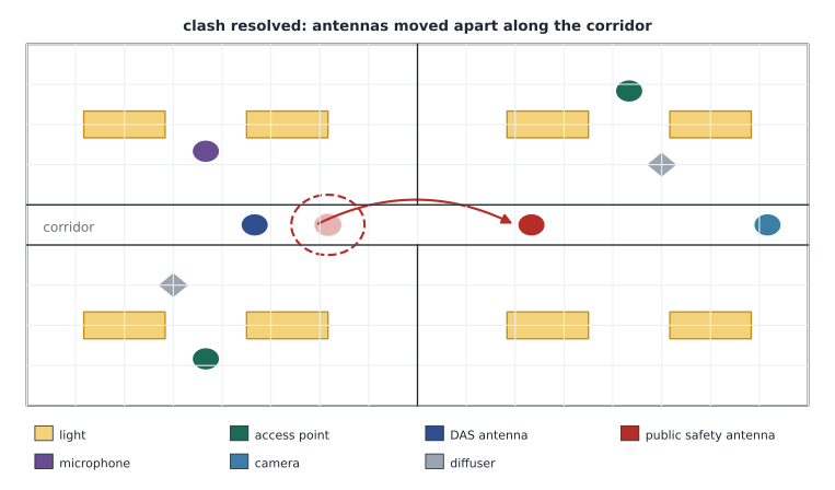
At the Harbourview workshop, the ceiling plan reveals typical clashes: a public safety antenna and a DAS antenna within a meter of each other in the corridor, an access point directly beside a light fixture with a metal housing, ceiling microphones above a supply diffuser in the lecture hall and a camera whose view is blocked by a hanging display. Each is resolved by moving one device and recording the change in the device schedule.
Coordinate pathways
Every special system adds cables to the pathways. Daniel's pathway calculations from the spaces and pathways course assumed office cabling densities; with access points, cameras, building automation, AV, nurse call, RTLS and PoE lighting added, the main corridor cable trays on the clinic floors carry nearly three times the original count. Some systems also bring different cable types: coaxial cable for the DAS, fire-rated cable or rated pathways for the public safety backbone, multi-conductor cable for door hardware and intrusion detection, and speaker cable for AV. The integrated design checks tray fill, separation, bend radius, support spacing and bundle sizes for PoE against the combined load.
Worked problem
Corridor tray fill on the clinic floor
The main corridor tray on the second floor is 300 mm wide by 100 mm deep, with a usable cross-section of 30,000 mm². The design limits fill to 40 of every 100 parts of the cross-section to leave room for growth and heat dissipation. The tray will carry 360 Category 6A cables with an outside diameter of 7.5 mm. Does it fit?
Show solution
- Area of one cable: π × (7.5 ÷ 2)² ≈ 3.1416 × 14.06 ≈ 44.2 mm².
- Total area: 360 × 44.2 ≈ 15,900 mm².
- Allowed area: 30,000 × 0.40 = 12,000 mm².
- 15,900 exceeds 12,000, so the tray is overfilled.
Answer: It does not fit. Daniel either widens the tray to 450 mm, which allows 18,000 mm², or splits the cables between two trays. Because many of the cables carry PoE, he also prefers a second tray to keep bundles smaller.
Coordinate spaces, power and cooling
Telecommunications rooms grow with every special system. Switches for access points, cameras, building automation and AV; door controllers and intrusion panels; DAS remote units; nurse call equipment; UPS units; and perhaps PoE lighting nodes all need rack and wall space. Each adds electrical load and heat. The integrated design produces a room-by-room table of equipment, power, UPS runtime and heat load, which goes to the electrical and mechanical engineers. Harbourview's second-floor room needs to grow by about a third compared with Daniel's first layout, and the clinic's rooms need essential power, as lesson 9 explained.
Worked problem
Room loads on the second floor
The second-floor telecommunications room will hold switches with a PoE load of 2,900 W and their own consumption of 450 W, a DAS remote unit of 180 W, door and intrusion panels of 150 W and a nurse call controller of 120 W. What is the total electrical load, and what is the UPS energy for 15 minutes of runtime?
Show solution
- Total load: 2,900 + 450 + 180 + 150 + 120 = 3,800 W.
- UPS energy for 15 minutes: 3,800 × 0.25 = 950 Wh, before losses.
Answer: About 3.8 kW of load and roughly 950 Wh of UPS energy, plus allowances. These figures replace the much smaller office-based estimate from early design.
Coordinate networks and security
Special systems share switches and backbone, so the network design must give each its own segment, access rules and quality of service. Voice and video traffic need priority; security and medical devices need isolation; building automation needs controlled remote access; and public safety interfaces must not depend on commercial network equipment where codes or the fire service forbid it. The RCDD works with the owner's network team to align the physical design, such as which switches serve which systems and which backbone paths are redundant, with the logical design. The device schedule's network segment column becomes the basis for switch port configuration and labeling.
Coordinate responsibilities and contracts
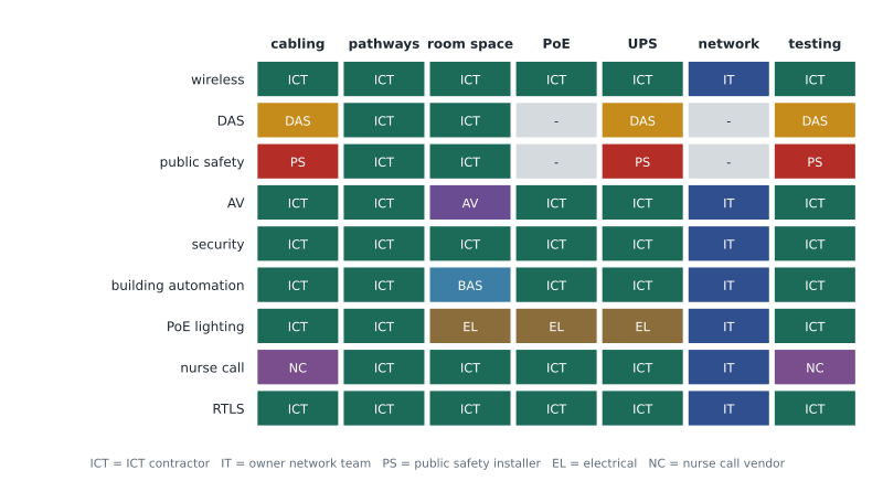
Special systems are often installed by different contractors under different contracts, sometimes after the main building contract. Each interface between them is a risk. A responsibility matrix, like the one Roz used for AV in lesson 4, should cover every special system: who provides each cable, pathway, box, enclosure, device, power supply and network port; who installs, terminates, tests and documents it; and who commissions the system as a whole. The specification should require each contractor to follow the building's labeling, testing and documentation standards so that the finished building has one consistent record.
Document once, for everyone
Integration ends with documentation. Every outlet, cable, port, pathway and space should be labeled under one administration scheme following TIA-606, recorded in drawings and records that show which system uses each, and handed over in a form the owner can maintain. For special systems this matters even more than for ordinary cabling, because their devices are scattered in ceilings and walls where they are hard to trace. Accurate documentation supports maintenance, security, troubleshooting and future change, and it is often the deliverable an owner values most years after construction.
A checklist before tender
Before the drawings leave the office, Roz and Daniel run through a checklist for special systems. Is every device in the master schedule shown on the drawings with its outlet and pathway? Does the ceiling plan resolve every clash? Do tray and conduit fills, separation and bundle sizes work with all systems included? Do telecommunications rooms have the space, power, UPS, cooling and essential power the room tables require? Are the public safety pathways rated and the monitoring interfaces shown? Are DAS spaces, roof access and riser sleeves reserved? Are network segments and reliability tiers agreed? Does the responsibility matrix cover every interface? Is there spare capacity for the systems not yet designed? Only when every answer is yes do they issue the package.
Designing for systems not yet chosen
Some special systems are not designed until late in a project, and some will not exist until years after the building opens. A building owner may decide on PoE lighting after the cabling is installed, add RTLS in a second phase or replace a DAS with a new technology. The integrated design cannot predict every change, but it can make change possible. Spare pathway capacity, typically planned as a share of each tray and riser, room space and power reserved for future racks, spare ceiling grid outlets and documented assumptions in the design basis all reduce the cost of systems that arrive later. Roz calls this designing for the unknown tenant, even in a building where the tenants are known.
The design basis is the place to record these decisions. For each special system it should state what is included now, what is assumed for the future and what capacity has been reserved. When a future designer opens the record drawings and asks why a riser has six empty sleeves or why a room has an empty rack, the design basis gives the answer. Without it, spare capacity is often used up by the first convenient project.
Exam focus: integration
Integration questions on the exam often describe a problem found during construction or after occupancy, such as antennas clashing in a ceiling, an overfilled tray or a telecommunications room without enough cooling, and ask what should have been done. The best answer usually names an integration step: a master device schedule, a coordinated reflected ceiling plan, combined pathway calculations, room load tables, a responsibility matrix or a single documentation standard. Calculation questions may ask for tray fill, UPS energy or total room load; work them step by step and check the units.
Finally, remember that integration is a process, not a single drawing. The master schedule, ceiling plan and room tables must be updated every time a system designer changes something, right through construction. An integration workshop at the end of design is valuable, but only if the results are carried into the documents and maintained until handover.
Common mistakes
MistakeReviewing each special system separately.
InsteadClashes appear only when all systems are combined. Use one device schedule and one coordinated ceiling plan.
MistakeSizing pathways and rooms from office cabling estimates.
InsteadSpecial systems can double or triple cable counts, PoE loads and room equipment. Recalculate with everything included.
MistakeLetting each contractor document its own system its own way.
InsteadRequire one labeling, testing and documentation standard for every system.
MistakeLeaving no spare capacity for systems not yet designed.
InsteadReserve pathway, room space and power for future systems and changes.
Summary and key terms
- An RCDD adds the most value by integrating all special systems into one infrastructure design.
- A master device schedule drives outlet counts, ports, PoE, UPS, network segments and responsibilities.
- Coordinated ceiling plans, combined pathway calculations and room load tables find conflicts before construction.
- Network segmentation, reliability tiers and a responsibility matrix align physical design with operation and contracts.
- One administration scheme and complete documentation make the building maintainable for decades.
- Master device schedule
- A single list of every connected device with location, cabling, power, reliability and responsibility.
- Reflected ceiling plan
- A drawing of the ceiling showing every device and fixture as seen from below.
- Integration workshop
- A meeting of all system designers to review a combined design and resolve conflicts.
- Room load table
- A table of equipment, power, UPS runtime and heat for each telecommunications room.
- Responsibility matrix
- A table assigning each part of each system to the party that provides, installs, terminates and tests it.
- Administration scheme
- The labeling and record-keeping system for the whole infrastructure, following TIA-606.
Practice problems
Work each problem on paper first, then reveal the answer to check.
A tray has 20,000 mm² of usable area and a 40 per 100 fill limit. How much cable area is allowed?
Show answer
8,000 mm².
A room has 2,500 W of load and needs 15 minutes of UPS. How much energy?
Show answer
625 Wh.
Name three items on a pre-tender special systems checklist.
Show answer
Every device shown with outlet and pathway; ceiling clashes resolved; rooms with enough space, power and cooling.
Lesson quiz · 5 questions
Score 60% or more to complete this lesson.
Create a free account to save your progress, take quizzes and earn a certificate.