
RCDD-113 · Lesson 8 of 12 · 19 min
Surge protection devices
▶ Video coming soon A video version of this lesson is on the way.
By early November, the electrical engineer's drawings showed surge protective devices at the main switchboard and at the panel serving the data room. Priya Raman asked Daniel to review them from the ICT side and to tell her what surge protection the telecommunications design needed beyond the entrance protectors. 'Protectors handle the copper coming in from outside,' she said. 'But surges also come in on the power, and some get made inside the building. I want one coordinated scheme, not two that ignore each other.'
A surge protective device, or SPD, is a device that limits transient overvoltages on a circuit by diverting surge current and clamping the voltage. The entrance protectors in lesson 7 are a kind of SPD for communications circuits. This lesson covers SPDs on AC power circuits, which are designed by the electrical engineer but matter enormously to ICT equipment, and SPDs on data and coaxial circuits within and around the building, which are often the RCDD's responsibility.
Where surges come from
Lesson 6 described surges from lightning and power faults outside the building. Power circuits bring their own: lightning on the utility's distribution lines, utility switching operations such as capacitor bank switching, and faults elsewhere on the utility system. Inside the building, surges are generated every day by the switching of inductive loads such as motors, elevators, chillers, transformers and the power supplies in electronic equipment itself. Internal surges are smaller than lightning surges but far more frequent, and over years they degrade electronics and cause unexplained resets and failures.
Because surges arrive on every kind of conductor, a scheme that protects only one path leaves the equipment exposed through another. A network switch with protected power but unprotected data cables to an outdoor camera, or protected data lines but an unprotected power supply, can still be damaged by the difference between the protected and unprotected sides. The principle is to protect every conductor that enters the protected zone, and to bond all the protective devices to the same reference.
SPD types on AC power
SPDs for AC power are classified by where they can be installed. In the United States, SPDs are listed to UL 1449, and the NEC's requirements for them are in Article 242, which replaced the older surge arrester and SPD articles. Both use the same broad types.
| Type | Where it is installed | Typical role | Harbourview example |
|---|---|---|---|
| Type 1 | Line or load side of the service disconnect, without needing an external overcurrent device | Service entrance protection against large external surges | Main switchboard, level 1 electrical room |
| Type 2 | Load side of the service disconnect, including branch panels | Distribution protection; also limits internally generated surges | Panels serving the data room, UPS input and each TR panel |
| Type 3 | Point of use, at least a set conductor length from the panel | Final stage for sensitive equipment | Plug-in surge strips and PDUs with SPD modules in racks |
| Type 4 and component | Parts or modules built into other equipment | Inside assemblies | SPD modules inside PDUs and UPS units |
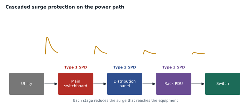
A well-designed scheme uses them in cascade. A Type 1 SPD at the service limits the large surges arriving from the utility. Type 2 SPDs at distribution panels catch what remains and limit surges generated inside the building. Type 3 devices at the equipment provide a final stage. Each stage reduces the surge further, and the impedance of the wiring between stages helps the downstream device and the upstream device share the energy instead of the smallest device trying to take it all.
Recent editions of the NEC require SPDs in some installations, for example at the services of dwelling units and on emergency systems, and adopting jurisdictions add their own requirements, so the electrical engineer confirms what the adopted code requires. For ICT spaces, owners and designers commonly go beyond the minimum.
Reading an SPD rating
SPD data sheets list several ratings, and an RCDD reviewing a design needs to know what they mean. The maximum continuous operating voltage, MCOV, is the highest voltage the SPD can withstand continuously without conducting; it must be above the highest normal voltage on the system, with margin for regulation and swells. The voltage protection rating, VPR, is a measured clamping voltage under a standard test; lower is better, but it must be compared at the same test conditions. The nominal discharge current, In, is the surge current the device can pass repeatedly under test; higher values indicate more robust devices. The short-circuit current rating must be at least the fault current available where the SPD is installed. The modes of protection tell which pairs of conductors the device protects: line to neutral, line to ground, neutral to ground and line to line.
US systems commonly use 120/208 V and 277/480 V three-phase services, and an SPD must be chosen for the specific system voltage and configuration. An SPD rated for the wrong system, or with an MCOV too close to the normal voltage, may conduct during normal swells, overheat and fail.
Lead length matters most
The most common way to defeat a good SPD is to install it with long leads. An SPD clamps the voltage at its own terminals. The equipment sees that voltage plus the voltage developed along the conductors that connect the SPD to the circuit and to ground. As lesson 6 showed, a fast surge current develops a large voltage along even a short length of conductor through its inductance. A panel-mounted SPD with three feet of loosely routed leads can let several hundred volts more through than its rating suggests.
# Let-through voltage at the equipment = SPD clamping voltage + voltage along its leads (L * di/dt)
vpr = 700                 # V, the SPD's measured clamping voltage at its terminals
di_dt = 3000 / 8e-6       # A/s: a 3 kA surge rising in 8 microseconds, a common test shape
L_per_m = 1.0e-6          # henries per m for a single conductor, a common estimate
for lead_m in (0.15, 0.3, 0.6, 1.0):
    v_leads = L_per_m * (2 * lead_m) * di_dt     # two leads: to the phase and to ground
print(f"leads {lead_m:4.2f} m each: let-through about {vpr + v_leads:6.0f} V")leads 0.15 m each: let-through about 812 V leads 0.30 m each: let-through about 925 V leads 0.60 m each: let-through about 1150 V leads 1.00 m each: let-through about 1450 V
The calculation is approximate, but the lesson is real: in this example every foot added to each lead adds more than 200 volts at the equipment. Installation practice is to mount the SPD as close as possible to the panel bus, ideally directly on the panel or with an integrated SPD, to keep the leads short and straight, and to twist the leads together to reduce the loop area. Daniel asked Priya to add a note on the electrical drawings requiring panel SPDs to be installed with the shortest possible leads, not exceeding the maker's maximum, and to prefer panels with integrated SPDs for the TR and data room panels.
SPDs on data and coaxial circuits
Data circuits that leave the protected zone need SPDs too. The most common case in modern buildings is Ethernet cabling to outdoor devices: security cameras on poles, wireless access points on exterior walls, parking gate controllers and building automation sensors. These cables are often powered over Ethernet, so the SPD must pass PoE power while clamping surges on the pairs. A data-line SPD for Ethernet is a small unit with a jack on each side and a ground terminal that must be bonded to the nearest busbar or bonded metal.
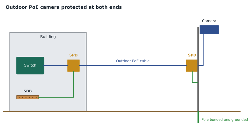
For an outdoor PoE device, good practice is an SPD at each end: one where the cable enters the building, bonded to the SBB or PBB, and one at the device, bonded to the pole or mounting structure, which is itself bonded and grounded. The SPD at the building protects the switch; the one at the device protects the camera. A single SPD at one end leaves the other end exposed. Shielded outdoor cable, bonded at both ends through the SPDs, further reduces induced surges.
Coaxial circuits for antennas, CCTV over coax and broadband services use coaxial SPDs, which must match the cable's impedance and frequency range so that they do not degrade the signal. Antenna SPDs for cellular and radio systems are often quarter-wave stub devices, which pass radio frequencies while shorting low-frequency surge energy to ground, or gas tube devices with a DC block. The DAS and radio equipment makers specify which kind is compatible.
The ground lead of a data-line SPD follows the same rule as a power SPD's leads. A data SPD mounted on a backboard with a long, coiled ground wire to a distant busbar lets through far more than its rating. Daniel's details placed the building-end SPDs for outdoor circuits on a small bonded plate beside the wall penetration, with a short conductor to a busbar extension from the SBB, so that each SPD's ground path was a few centimeters rather than a few meters. The same principle applies to the protectors in lesson 7: the protection is only as good as the path to the reference.
The Harbourview scheme
Daniel and Priya agreed on a single coordinated scheme. On power: a Type 1 SPD at the main switchboard; Type 2 SPDs integrated in the panels serving each TR, the data room and the UPS input; and Type 3 protection in the rack PDUs for critical equipment. On communications: primary protectors on the copper entrance cable, secondary protection at the cross-connect, coaxial protectors on all antenna feeds at the rooftop enclosure, and Ethernet SPDs at both ends of the four outdoor camera circuits and the two exterior wireless access points. Every SPD's ground terminal was bonded to the nearest busbar in the telecommunications bonding network or to the panel ground bus bonded to it.
The parking lot cameras' poles had their own small grounding electrodes, as the electrical code required for the pole lighting circuits. Priya confirmed that those electrodes were bonded to the building grounding system through the equipment grounding conductors of the pole circuits, so the cameras' SPDs and the building's SPDs shared a common reference, though a distant one. Daniel noted in the design file that the pole SPDs were important precisely because the poles were at the far end of long conductors from the building.
Maintaining SPDs
SPDs wear out. Each large surge degrades the metal oxide varistors that most power SPDs use, and a device that has absorbed many surges may fail open, leaving equipment unprotected without anyone knowing. Most panel SPDs have status indicators, and many have dry contacts that can be monitored by the building management system. Daniel's specification required SPD status contacts on all Type 1 and Type 2 devices to be connected to the building management system, with alarms to the facilities team, and included SPD checks in the annual maintenance plan described in lesson 12.
Worked problem
Choosing protection for an outdoor access point
A wireless access point is to be mounted on the exterior wall of Harbourview above the main entrance, fed by a PoE cable about 25 meters long from TR-1. What protection and bonding should be specified?
Show solution
- The cable leaves the building envelope to an exterior device, so it is exposed to induced surges and, on the exterior wall, to nearby strikes.
- Specify a PoE-rated Ethernet SPD where the cable passes through the exterior wall, bonded to the TR-1 SBB or to a bonded busbar extension near the wall penetration.
- Specify a second PoE-rated SPD at the access point, bonded to the mounting bracket, with the bracket bonded to the building steel or to a bonding conductor from TR-1.
- Use outdoor-rated cable, shielded if the access point and SPDs support it, with the shield bonded through the SPDs at each end.
Answer: PoE-rated SPDs at both ends, each bonded locally, with an outdoor-rated, preferably shielded cable.
Common mistakes
MistakeProtecting the power but not the data cables to outdoor devices.
InsteadProtect every conductor entering the protected zone and bond all SPDs to the same reference.
MistakeInstalling a panel SPD with long, loose leads.
InsteadMount it at the panel with the shortest, straightest leads, or use an integrated SPD.
MistakeComparing clamping voltages from different tests.
InsteadCompare VPR values measured under the same standard test.
MistakeAssuming an SPD lasts forever.
InsteadMonitor status indicators and include SPDs in maintenance.
Summary and key terms
- SPDs limit transient overvoltages by diverting surge current; surges come from outside and are generated inside the building.
- AC SPDs are Type 1 (service), Type 2 (distribution) and Type 3 (point of use), used in cascade.
- Key ratings are MCOV, VPR, nominal discharge current, short-circuit current rating and modes of protection.
- Lead length adds voltage at surge rise times; keep leads short and straight.
- Outdoor PoE and coaxial circuits need SPDs suited to the signal, usually at both ends, each bonded locally.
- Monitor SPD status, because devices degrade with each surge.
- Surge protective device (SPD)
- A device that limits transient overvoltages by diverting surge current.
- MCOV
- Maximum continuous operating voltage: the highest voltage an SPD withstands continuously without conducting.
- Voltage protection rating (VPR)
- A standard measure of an SPD clamping voltage under test.
- Nominal discharge current
- The surge current an SPD can pass repeatedly under test.
- Metal oxide varistor
- A voltage-dependent resistor used in most power SPDs, which degrades with repeated surges.
- Quarter-wave stub protector
- An antenna SPD that passes radio frequencies and shorts low-frequency surge energy to ground.
Practice problems
Work each problem on paper first, then reveal the answer to check.
Where are Type 1, Type 2 and Type 3 SPDs installed?
Show answer
Type 1 at the service, Type 2 at distribution panels, Type 3 at the point of use.
Why does SPD lead length matter?
Show answer
Lead inductance adds voltage during fast surges, raising the let-through voltage.
What protection does an outdoor PoE camera need?
Show answer
A PoE-rated data SPD at each end, each bonded to the local reference.
Why should SPD status be monitored?
Show answer
SPDs degrade with each surge and can fail without obvious signs.
Lesson quiz · 5 questions
Score 60% or more to complete this lesson.
Create a free account to save your progress, take quizzes and earn a certificate.