
RCDD-113 · Lesson 3 of 12 · 20 min
The telecommunications bonding infrastructure
▶ Video coming soon A video version of this lesson is on the way.
With the vocabulary settled, Daniel opened the architectural floor plans for Harbourview and started laying out the bonding network. The building has four stories above grade. The main electrical room is on level 1 at the north-east corner, next to the loading dock. The entrance facility, where the service provider cables and the campus link from the existing clinic building arrive, shares a room with the main equipment room immediately west of the electrical room. Telecommunications rooms are stacked one above another on levels 1 to 4 near the central core, and a small data room on level 2 holds the clinic's servers and the college's teaching lab equipment.
'Start where the energy comes in and where it leaves,' Roz said. 'The energy comes in on the outside cables at the entrance facility. It leaves to earth through the electrical service's grounding electrode system next door. Put the primary bonding busbar between those two, as close to both as you can, and the rest of the network hangs off it.'
The building blocks
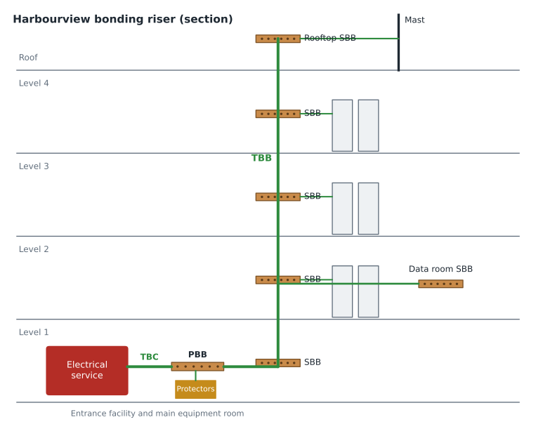
The telecommunications bonding infrastructure defined by ANSI/TIA-607 has a simple structure. One primary bonding busbar, the PBB, serves the building. A telecommunications bonding conductor, the TBC, connects the PBB to the electrical service grounding. A telecommunications bonding backbone, the TBB, runs from the PBB through the building's backbone pathways to a secondary bonding busbar, an SBB, in each telecommunications room and other ICT space. Where a building has more than one backbone, backbone bonding conductors, BBCs, tie them together. Within each room, racks, cable trays, cable shields and protector grounds connect to the local SBB, or to the PBB in the room that has it.
The structure is a tree with a single root. Every path from any piece of ICT metal leads back through the SBB and TBB to the PBB and then through the TBC to the electrical service. That single root is what gives the network its single, controlled connection to the electrical system. The backbone bonding conductors and the bonding of busbars to building steel add parallel paths that lower impedance, but they do not create a second connection to a separate earth.
Locating the PBB
The PBB should be in the entrance facility or main equipment room, mounted where it is accessible and as close as practical to the electrical service and to the point where outside plant cables enter. Every protector at the entrance must be bonded to it with a short, direct conductor, so a PBB on the far side of a large room from the protectors defeats much of its purpose. On Harbourview the entrance facility and the electrical room share a wall, so Daniel placed the PBB on that wall, about 6 feet from the protector field and about 10 feet from the service equipment through the wall.
Short is not the only goal. The TBC and the protector bonding conductors should be as straight as possible, because every bend adds inductance and makes a surge current more likely to jump across to nearby metal. Where a bend is needed, a sweeping bend with a generous radius is better than a sharp corner. Daniel's layout ran the TBC through a sleeve in the shared wall at the same height as the PBB and the service ground bus, with no vertical offsets.
The PBB should also be bonded to the building's structural steel where the steel is accessible in the room, and to any metallic water pipe that serves as part of the grounding electrode system if it is nearby. These connections are additional to the TBC. They help keep the PBB and the building's metal at the same potential.
The TBC and the connection to the electrical system
The TBC is the most important single conductor in the network. It connects the PBB to the electrical service's grounding, at the service equipment ground bus, the intersystem bonding termination described in 250.94 of the NEC, or the grounding electrode conductor, depending on the arrangement and on what the code and the AHJ accept. It must be at least as large as the largest TBB it serves, and it is usually installed by the electrical contractor because it connects to the electrical system.
Priya Raman's service design for Harbourview placed a dedicated ground bus in the main electrical room for other systems' bonding conductors. Daniel's drawings showed the TBC from the PBB to that bus, labeled to match Priya's drawing, with a note that the electrical contractor would install it. Both drawings referenced a shared detail showing the conductor size, the type of connector at each end and the label to be applied.
The telecommunications bonding backbone
The TBB connects the PBB to each SBB. It is a continuous insulated copper conductor that normally follows the backbone cabling pathway, so that it stays close to the backbone cables it helps protect. Keeping the TBB alongside the cables matters: if a surge current is flowing on cable shields, a nearby bonding conductor carries a share of it and keeps the shield voltages down. A TBB routed separately up a different shaft does much less.
At each floor the TBB connects to the SBB with a short tap. The TBB itself should be continuous from the PBB to the farthest SBB. Splices should be avoided; where one is unavoidable, it should be made with an irreversible compression connector or exothermic weld. The TBB is not a grounding electrode conductor and does not need to connect to any ground rod or electrode along the way.
A TBB is not a substitute for the building's steel, and the building's steel is not a substitute for the TBB. Metal water pipes, the building frame and cable trays all have some value as parallel paths, but their continuity cannot be relied on: joints are painted, pipes are replaced with plastic, trays are modified. Older guidance allowed building steel to serve as the backbone in some cases; current practice treats a dedicated TBB as the primary path and the steel as a supplement.
Secondary bonding busbars
Each telecommunications room, equipment room and other ICT space without the PBB gets an SBB. It is the local reference to which everything in that room is bonded: the rack bonding conductors, cable tray and ladder rack, the shields of shielded cables that terminate in the room, any protectors for cables entering the room from outside, and the room's power panel if one is present. On Harbourview, Daniel placed an SBB in each of TR-1 to TR-4 and in the level 2 data room.
The SBB should be mounted near the backbone pathway entry to the room, so that the TBB tap is short, and at a height that is accessible but out of the way of equipment. A common location is on the backboard wall near the ceiling, above the cable ladder, or at the bottom of the wall near where the riser sleeves come through the floor. Roz preferred to keep it on the wall near the sleeves with clear space above for future conductors.
Where a telecommunications room has its own electrical panel, the SBB should be bonded to that panel's equipment ground bus. That connection reduces the voltage difference between the power and telecommunications references in the room. It does not create a problematic second path, because both systems are already connected at the service.
| Space | Busbar | Connects to | Notes |
|---|---|---|---|
| Entrance facility and main equipment room | PBB | TBC to the service ground bus; TBB; protectors; building steel | One per building, beside the electrical room |
| TR-1 to TR-4 | SBB | TBB tap; racks; trays; shields; room panel ground bus | Stacked in the core above the entrance facility |
| Level 2 data room | SBB | TBB tap; mesh bonding network; racks; room panel and UPS | Larger busbar for the equipment room mesh |
| Rooftop antenna enclosure | SBB | TBB extension; antenna cable bonding; mast bond | Added for the cellular and two-way radio systems |
Multiple backbones and backbone bonding conductors
In a tall or wide building, the backbone cabling often runs in more than one riser, and each riser gets its own TBB. Those TBBs all start at the PBB, but over many floors their potentials can drift apart, especially during a surge. Backbone bonding conductors connect SBBs in different risers on the same floor, typically at the top floor and at regular intervals below, so that parallel backbones act as one system. ANSI/TIA-607 gives the conditions under which BBCs are required and how often; the designer should read the current revision rather than relying on a rule of thumb.
Harbourview has a single riser through the core, so it needs no BBC between backbones. But the building has a second vertical path for one service: the rooftop cellular and two-way radio antennas, whose coaxial cables come down a separate shaft on the east side to the level 4 telecommunications room. Daniel extended the TBB from the level 4 SBB to a small SBB in the rooftop antenna enclosure, so that the antenna cables could be bonded where they enter the building at the top, and bonded that rooftop SBB to the roof steel. Lessons 6 and 7 come back to why antenna cables need bonding at both ends.
Campus and multi-building systems
The 400-meter campus link to the existing clinic building introduces a second building with its own electrical service and grounding electrode system. Each building must have its own PBB bonded to its own service. The two buildings are not bonded together through a telecommunications conductor; their electrical systems and grounding electrodes are separate, and during a lightning strike the two can differ by thousands of volts.
That difference is exactly why cables between buildings need protection. A copper cable running between them connects two points that may be far apart in potential. The entrance protectors in each building, bonded to each building's PBB, limit the voltage on the copper pairs, and the cable's metallic shield must be bonded at each entrance so that surge current flowing on it is carried to ground at both ends. Roz recommended making the campus link entirely optical fiber with no metallic members, which removes the conductive path between buildings and eliminates most of the hazard. Lesson 7 covers the cases where metal in a fiber cable still needs bonding.
What the infrastructure is not
Daniel's first draft included a ground rod outside the entrance facility, connected directly to the PBB. Roz struck it through. 'A separate electrode on the PBB creates a second path to earth that is not bonded to the electrical system's electrode at the same point. If the code or the AHJ requires an additional electrode for some reason, it must be bonded to the building's grounding electrode system, and the electrical engineer decides that.' The same reasoning ruled out a separate rod at the base of the antenna mast: the mast is bonded to the roof steel and through the rooftop SBB to the network, and the building's lightning protection system, designed by the electrical engineer, provides the down conductors to earth.
Worked problem
Building the busbar schedule
List every busbar Harbourview needs and what the main conductors connect, from the outside cable entrance to the rooftop.
Show solution
- Entrance facility: one PBB on the shared wall with the electrical room.
- TBC: PBB to the service ground bus provided for other systems, installed by the electrical contractor.
- TBB: from the PBB up the core riser to SBBs in TR-1, TR-2, TR-3 and TR-4, with a branch tap to the level 2 data room SBB.
- Rooftop: the TBB continues from the TR-4 SBB to an SBB in the antenna enclosure, bonded to roof steel.
- Campus link: the existing clinic building gets its own PBB bonded to its own service, and the link is specified as all-dielectric fiber.
Answer: Six busbars at Harbourview (one PBB and five SBBs), one TBB with taps, one TBC and a separate PBB in the existing building.
Common mistakes
MistakePlacing the PBB wherever there is free wall space.
InsteadLocate it in the entrance facility or main equipment room, close to both the protectors and the electrical service.
MistakeRouting the TBB up a different shaft from the backbone cables.
InsteadRun the TBB alongside the backbone cabling it protects.
MistakeAdding a separate ground rod to the PBB.
InsteadConnect the ICT network to earth only through the electrical service; any extra electrode must be bonded into the building's electrode system.
MistakeBonding two buildings together with a telecommunications conductor.
InsteadGive each building its own PBB bonded to its own service, and protect or eliminate conductive paths between them.
Summary and key terms
- The bonding infrastructure is a tree: PBB, TBC to the service, TBB to SBBs, with BBCs between parallel backbones.
- Place the PBB in the entrance facility or main equipment room, close to protectors and the electrical service.
- The TBC is the single controlled connection to the electrical system and is at least as large as the largest TBB.
- Run the TBB continuously alongside the backbone cabling, avoiding splices.
- Every ICT space other than the PBB room gets an SBB, bonded to the room's panel ground bus where one exists.
- Each building has its own PBB; conductive cables between buildings need protection at both ends, and dielectric fiber avoids the problem.
- Single-point connection
- The principle that the ICT bonding network connects to the electrical grounding system at one controlled point.
- TBB tap
- A short conductor from the backbone to an SBB.
- Exothermic weld
- A permanent, low-resistance connection made by a chemical reaction that melts copper into a mold around the conductors.
- Irreversible compression connector
- A connector crimped with a specified tool and die so that it cannot be removed without being cut.
- All-dielectric cable
- An optical fiber cable with no metallic components.
Practice problems
Work each problem on paper first, then reveal the answer to check.
Where should the PBB be located?
Show answer
In the entrance facility or main equipment room, as close as practical to the protectors and the electrical service.
Why should the TBB follow the backbone cable pathway?
Show answer
So it shares surge current with nearby cable shields and keeps their voltage down.
Why does a separate ground rod on the PBB cause problems?
Show answer
It creates a second path to earth not bonded at the same point as the electrical system's electrode.
How should the Harbourview campus link avoid conductive paths?
Show answer
By using all-dielectric optical fiber cable.
Lesson quiz · 5 questions
Score 60% or more to complete this lesson.
Create a free account to save your progress, take quizzes and earn a certificate.