
RCDD-112 · Lesson 3 of 12 · 24 min
Work areas and outlet density
▶ Video coming soon A video version of this lesson is on the way.
The owner's project manager for Harborview sends a one-line request: two data jacks per desk. Roz reads it aloud to Daniel and asks what is missing. He starts a list. Clinic exam rooms do not have desks. Classrooms need outlets for projectors, lecterns and wall displays. Wireless access points need cabling in the ceiling. Cameras, card readers, nurse call stations, digital signs, printers and building controllers all need connections. By the end of the morning his list has nineteen outlet types, and the owner's one line has become a table. That table is what this lesson is about.
What a work area is
In cabling standards, a work area is the space where occupants use telecommunications equipment: an office, a cubicle, a classroom seat cluster, an exam room, a reception desk. The work area begins at the equipment outlet and includes the cords and equipment that plug into it. The horizontal cabling ends at the outlet, so anything on the work area side, such as a cord, adapter or desk-mounted switch, belongs to the user's equipment rather than to the cabling plant.
For planning, ANSI/TIA-569 uses a work area size of about 10 square meters (100 square feet) of usable floor space when the actual furniture layout is not yet known. Usable space excludes corridors, washrooms, shafts, mechanical rooms and stairs. A floor with 1,800 square meters of usable office space would therefore be planned for about 180 work areas. When the architect supplies a furniture plan, the designer counts real positions instead, and the planning figure becomes a check on whether the plan seems reasonable.
The minimum outlet count
ANSI/TIA-568.1 requires at least two equipment outlets per work area in a commercial building. Each outlet is served by its own 4-pair cable or fiber pair, run as a separate home run to the telecommunications room. At least one of the two must be balanced twisted pair, and the other may be twisted pair or fiber. Many owners specify more, because two outlets at a desk are quickly taken by a computer and a phone, and a docking station, a second computer or a desk camera then needs a third.
The minimum is a floor, not a design. Roz tells Daniel to think about outlet density in terms of devices, not desks. A modern work area may have a laptop on wireless, a desk phone that is really a softphone, two monitors that need no network at all and a docking station that does. The real question for each space is which devices need a wired connection there for the life of the cabling, including devices that do not exist yet.
Outlet types beyond the desk
Much of today's horizontal cabling serves devices that have nothing to do with desks. Wireless access points are the largest group in most buildings. Security cameras, access control readers, intercoms, digital signage, audiovisual equipment, point-of-sale terminals, building automation controllers, lighting control and occupancy sensors are others. ANSI/TIA-862 and the ISO/IEC 11801 part for distributed building services describe a coverage-area approach for these devices, with service outlets placed on a grid in the ceiling so that a device can be added anywhere near one. RCDD-114 covers the systems themselves; this lesson counts the cables they need.
| Outlet type | Typical location | Usual media | Planning note |
|---|---|---|---|
| Desk or workstation | Wall, floor box or furniture feed | Category 6A | Two minimum per work area; often three or four. |
| Wireless access point | Ceiling, on a grid | Two Category 6A per location | The second cable allows future radios and higher power. |
| Security camera | Ceiling, wall or exterior | Category 6A or 6 | Locations set by the security consultant. |
| Access control reader | Beside doors | Category 6A or a composite cable | Coordinate with door hardware. |
| Display or projector | Wall or ceiling | Category 6A, sometimes fiber | AV systems may need several cables per location. |
| Building automation | Ceiling coverage-area outlets | Category 6A | Service outlets on a grid, as in ANSI/TIA-862. |
| Printer or copier | Wall near the device | Category 6A | Often forgotten; count one or two per copy room. |
Wireless access point grids
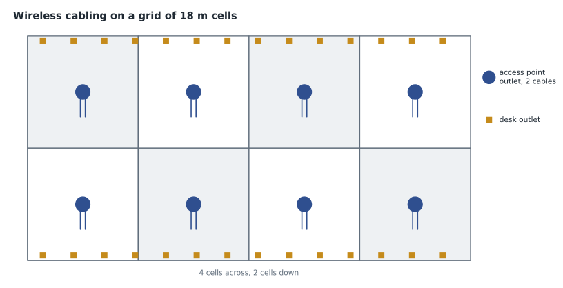
Because wireless designs change as devices change, many designers cable for access points on a regular grid rather than only at today's planned locations. TIA guidance for cabling to wireless access points describes a grid of cells about 18 meters (60 feet) on a side, with cabling to a point near the center of each cell and two Category 6A cables to each location. The wireless designer then places access points within reach of those outlets. When the wireless design is complete and the owner wants exact locations, the grid becomes a check that coverage will not run out as density rises.
Outlets in special environments
Some building types have their own standards for outlet counts. Health care facilities follow ANSI/TIA-1179, which recognizes that patient rooms, intensive care rooms and operating rooms need many more outlets than offices for monitors, pumps, nurse call, beds and clinical displays, and that clinical spaces need specific locations near beds and headwalls. Educational facilities follow ANSI/TIA-4966, which addresses classrooms, labs, lecture halls and dormitories. Residential buildings follow ANSI/TIA-570. Data centers follow ANSI/TIA-942, covered in RCDD-115. On a mixed-use building like Harborview, the clinic floors follow the health care guidance and the classroom floor follows the education guidance, while the offices follow the commercial building standard.
Regulators and owners may add requirements of their own. Clinical outlets may need to be on emergency power, and medical equipment may need outlets in particular places on a headwall. Classrooms may need outlets in the floor for flexible furniture. Accessible design rules in the ADA Standards for Accessible Design set the heights at which outlets and controls must be reachable. The designer must gather all of these before counting.
The outlet schedule
Roz's office turns the outlet list into an outlet schedule: a table that lists every room, its use, the number of each outlet type in it, and the media and category for each. The schedule is the bridge between the owner's needs and the drawings. It feeds the cable count for each telecommunications room, which in turn sizes the patch panels, switches, racks, pathways and power. It also gives the cost estimator the quantities for the bill of materials and the commissioning agent the list of links to test. On large projects the schedule lives in a spreadsheet or a design tool that generates the labels and the test plan automatically.
A good schedule records the reason for each outlet, not just the count. When a value engineering meeting asks which outlets can be cut to save money, the designer can show that a particular room's outlets come from a clinical standard, an accessibility rule or an owner requirement, and which ones are planned spares. Spares are not waste; lesson 11 explains why cutting them is usually false economy.
Outlet placement and mounting
Counting outlets is only half the work; placing them is the other half. Wall outlets are usually mounted at the same height as the power receptacles beside them, and both must meet the accessible reach ranges in the ADA Standards for Accessible Design and the building code adopted locally. Outlets for wall-mounted displays sit behind the display, often with a recessed box so that the plug does not push the screen away from the wall. Ceiling outlets for wireless access points and cameras are placed where the device will be mounted, with enough slack and a box or bracket that the device can be fixed to. Floor boxes serve desks in the middle of large rooms, and they must be coordinated with the structural engineer, because cutting a slab after it is poured is expensive and sometimes impossible.
Each outlet location also needs a pathway to it. A wall outlet needs a box and a conduit or open space in the stud cavity up to the ceiling; an outlet in a concrete or masonry wall needs a conduit set during construction. The cabling designer should mark every outlet type on the drawings with a symbol that the electrical contractor will recognize, because in many projects the electrical contractor installs the boxes and conduits even though the cabling contractor installs the cable. Missing boxes are one of the most common causes of delay and change orders on cabling projects.
Outlet faceplates have a limited number of ports, commonly one to six, and the designer chooses them by location. A classroom lectern with four outlets can use a single four-port plate; a desk with three outlets might use a four-port plate with one blank insert, leaving a spare position that a future cable can use without a new faceplate. Faceplates should carry the outlet identifiers described in lesson 12, printed rather than handwritten, so that a technician can find the matching port in the telecommunications room without a search.
Outlet counts should also be checked against the space that will hold their cables. A classroom with six outlets, two access point cables and a display needs nine cables through its door frame or ceiling, and a corridor serving twenty such rooms carries well over a hundred cables to the telecommunications room. The outlet schedule therefore feeds the pathway design directly, and a late increase in outlets can overfill a tray that was sized for the original count.
Worked problem
Counting outlets for an office floor
An office floor has 1,800 square meters of usable space and no furniture plan yet. The owner wants three outlets per work area. The floor measures 60 by 30 meters, and the wireless grid uses cells 18 meters on a side with two cables per cell. Twelve cameras and six card readers are also planned. How many horizontal cables are needed?
Show solution
- Work areas: 1,800 / 10 = 180.
- Desk outlets: 180 × 3 = 540 cables.
- Wireless cells: 60 / 18 = 3.3, so 4 cells across; 30 / 18 = 1.7, so 2 cells down; 4 × 2 = 8 cells.
- Wireless cables: 8 × 2 = 16.
- Security: 12 + 6 = 18 cables.
- Total: 540 + 16 + 18 = 574 cables.
Answer: About 574 horizontal cables. Rounding the wireless cells up, not down, keeps the corners of the floor covered.
Worked problem
Checking a room against its rack space
The telecommunications room for that floor will hold the 574 cables on 48-port patch panels. How many panels are needed, and how many rack units do they occupy if each 48-port panel is 2 rack units and the design adds one rack unit of horizontal cable manager for every panel?
Show solution
- Panels: 574 / 48 = 11.96, so 12 panels.
- Panel space: 12 × 2 = 24 rack units.
- Cable managers: 12 × 1 = 12 rack units.
- Total: 24 + 12 = 36 rack units, before switches and spare space.
Answer: Twelve panels taking 36 rack units, most of one standard rack. The switches for those ports need roughly the same space again, so this room needs at least two racks plus growth.
Daniel's outlet schedule for Harborview ends up with 1,412 horizontal cables across four floors, against the owner's original estimate of about 600 based on two jacks per desk. Roz takes the schedule to the next design meeting and walks the owner through each outlet type. The project manager approves it, adding that he wishes someone had shown him a table like this before the budget was set.
Common mistakes
MistakeCounting outlets only at desks.
InsteadCount every device type: wireless, security, AV, building systems and printers.
MistakeTreating the two-outlet minimum as the design.
InsteadTwo outlets per work area is the minimum; many spaces need more.
MistakeRounding wireless cells down.
InsteadRound up so the edges of the floor are covered.
MistakeUsing the commercial building standard for patient rooms.
InsteadHealth care spaces follow ANSI/TIA-1179, with much higher outlet counts.
MistakeKeeping the outlet list in an email.
InsteadBuild an outlet schedule that records type, media, count and reason for every room.
Summary and key terms
- A work area is the space where occupants use telecommunications equipment, beginning at the equipment outlet.
- ANSI/TIA-569 plans one work area for about 10 square meters (100 square feet) of usable space.
- ANSI/TIA-568.1 requires at least two outlets per work area, each a separate home run.
- Count outlets for devices, not desks: wireless, cameras, readers, displays, printers and building systems.
- Wireless cabling is often planned on a grid of cells about 18 m on a side, with two Category 6A cables per cell.
- Health care, education, residential and data center spaces have their own standards.
- The outlet schedule turns needs into counts that drive panels, racks, pathways and costs.
- Work area
- The space where occupants use telecommunications equipment.
- Equipment outlet
- The outlet where an end device connects to horizontal cabling.
- Outlet density
- The number of outlets per work area or per unit of floor area.
- Coverage area
- A ceiling zone served by a service outlet for building devices.
- Service outlet
- An outlet for building systems such as sensors and controllers.
- Outlet schedule
- A table listing every outlet by room, type, media and reason.
Practice problems
Work each problem on paper first, then reveal the answer to check.
How many work areas should be planned for 2,500 square meters of usable space?
Show answer
About 250.
What is the minimum number of outlets per work area?
Show answer
Two.
How many cables does TIA guidance suggest for each wireless access point location?
Show answer
Two Category 6A cables.
Which standard covers outlet counts in health care facilities?
Show answer
ANSI/TIA-1179.
A floor is 45 by 40 m. With 18 m wireless cells, how many cells are needed?
Show answer
3 across by 3 down, 9 cells.
Why record the reason for each outlet in the schedule?
Show answer
So value engineering decisions can see which outlets are required and which are spares.
Which standard covers residential cabling?
Show answer
ANSI/TIA-570.
Lesson quiz · 5 questions
Score 60% or more to complete this lesson.
Create a free account to save your progress, take quizzes and earn a certificate.