
RCDD-112 · Lesson 2 of 12 · 24 min
Horizontal cabling design
▶ Video coming soon A video version of this lesson is on the way.
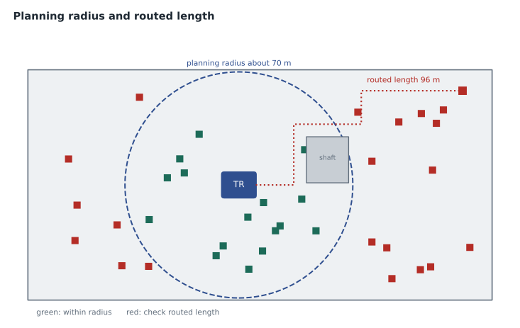
Daniel's second week begins on the third floor of Harborview, which is still a concrete deck with columns, a few framed walls and a lot of wind. Roz brings a measuring wheel, a set of architectural drawings and a question: if a clinic room in the far corner is 78 meters from the telecommunications room in a straight line, can it be served from that room? Daniel says yes, because the limit is 90 meters. Roz walks him along the route the cable would actually take, up into the ceiling, around a shaft, along a corridor, down a wall, and the wheel reads 96. That walk is the first lesson of horizontal design: distances are measured along the pathway, never across the drawing.
What horizontal cabling is
Horizontal cabling, Cabling Subsystem 1 in the TIA hierarchy, is everything between the equipment outlet and the horizontal cross-connect in the telecommunications room or enclosure. It includes the horizontal cable itself, the outlet and its connector, the termination at the cross-connect, any patch cords or jumpers used there, and an optional consolidation point. The name comes from the fact that on a typical floor these cables run horizontally in the ceiling or floor, although in tall rooms and atriums they may run vertically too. What makes cabling horizontal is its place in the topology, not its direction.
Horizontal cabling deserves the most design attention because it is the largest and least accessible part of the plant. A building may have a few dozen backbone cables and several thousand horizontal cables. Horizontal cables are buried in walls and ceilings, behind finishes that the owner does not want opened again, and they are the hardest part to replace when needs change. A backbone upgrade means pulling a few new fiber cables up a riser; a horizontal upgrade can mean rewiring every outlet in the building. Designers therefore choose horizontal media for the longest expected life.
Recognized horizontal media
The standards recognize a short list of horizontal media. The usual choice is 4-pair 100-ohm balanced twisted-pair cable, in Category 5e, 6 or 6A, with Category 6A recommended by TIA for new installations because it supports 10 gigabit Ethernet over the full 100 meter channel and handles higher Power over Ethernet currents with less heating. Multimode fiber with two or more strands, and singlemode fiber, are also recognized for horizontal use, and some designs run fiber to the desk or to wireless access points. Category 3 cable, coaxial cable and older shielded twisted-pair types are no longer recognized for new horizontal cabling.
In twisted-pair cabling, the cable and its connecting hardware must be of the same category or better. A Category 6A cable terminated on Category 6 jacks is only a Category 6 link. Mixed categories in one channel perform at the level of the lowest component, which is why specifications usually require a single manufacturer's tested system and a warranty that covers every component.
The length limits
Horizontal length is governed by two numbers that every RCDD candidate must know. The horizontal cable from the outlet to the cross-connect, called the permanent link when it is tested, may be no longer than 90 meters (295 feet). The complete channel, which adds the work area cord, any patch cords or jumpers in the telecommunications room and the equipment cord to the switch, may be no longer than 100 meters (328 feet). That leaves 10 meters (33 feet) for all the cords together. TIA also recommends that cords in the telecommunications room be no longer than 5 meters (16 feet).
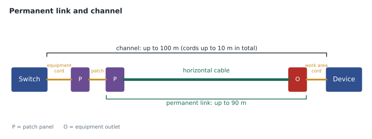
These limits apply to twisted-pair cabling for the applications the standards are designed around, chiefly Ethernet up to 10 gigabits per second. Fiber horizontal cabling follows the same 90 meter rule in TIA's commercial building standard so that the floor plan works for either medium, even though fiber itself can go much further. The physics behind the 100 meter channel, mainly insertion loss and crosstalk at the highest frequency of each category, is the subject of RCDD-110; lesson 7 of this course turns the limits into channel models.
Locating the telecommunications room
Because of the 90 meter limit, the location of telecommunications rooms is a cabling decision as much as a space decision. ANSI/TIA-569 calls for at least one telecommunications room per floor, and more when the floor area served exceeds 1000 square meters (10,000 square feet) or when horizontal runs would exceed 90 meters. Rooms should be as close to the center of the area they serve as the architecture allows, and stacked vertically from floor to floor so that backbone pathways are short and straight.
A useful planning rule is to sketch a circle around each room with a radius of about 70 meters on the floor plan. Inside that circle, almost every outlet can be reached within 90 meters once the cable has gone up into the ceiling, around obstacles and down a wall. Outlets near the edge of the circle need a walk with a measuring wheel or a careful routed measurement on the drawings, and outlets outside it need a second room. Roz's corner clinic room at 96 meters routed fails, so the design must either move the room, add an enclosure closer to that wing, or reroute the pathway.
Routing and separation
Horizontal cables should take the most direct route that the pathways allow, with enough support to avoid sagging and enough room to meet the manufacturer's bend radius, usually four times the cable diameter for 4-pair cable after installation. They should avoid sources of electromagnetic interference. Fluorescent and LED drivers, motors, transformers, variable frequency drives and power cables can all couple noise into twisted pairs. ANSI/TIA-569 gives separation guidance for telecommunications cabling near power, and the NEC sets minimum separations and barrier requirements for safety. Running a cable tray directly beside a busway or across the top of a large motor control center invites trouble even if it is legal.
Cables must also have the right fire rating for the space they pass through. In the United States, NEC Article 800 sets the listing hierarchy for communications cable: CMP for plenums, CMR for risers, CM for general use and CMX for limited residential use, with higher ratings allowed in place of lower ones. The ratings protect people by limiting flame spread and smoke, and an inspector will reject the wrong jacket even if the cable performs perfectly.
| Space | Typical requirement | Design note |
|---|---|---|
| Air-handling ceiling or raised floor | CMP plenum-rated cable | Confirm with the mechanical design whether the ceiling is used for return air. |
| Riser shaft between floors | CMR riser-rated cable, or CMP | Firestop every penetration; see RCDD-111. |
| General office walls and ceilings not used for air | CM general-purpose cable or higher | Many owners specify the higher rating everywhere to simplify stock. |
| Outdoors or underground | Cable listed for the environment, or indoor cable in a suitable raceway | Indoor cable cannot be run in wet locations. |
Slack and service loops
Every horizontal cable needs a little extra length so that it can be re-terminated if a jack is damaged, or so that a rack can be moved slightly. A common practice is to leave about 3 meters (10 feet) of slack in the telecommunications room for twisted-pair cable and about 0.3 meter (1 foot) at the outlet, with more for fiber, which needs a longer loop for splicing or re-termination. The slack counts toward the 90 meter limit, so a run that measures 88 meters to the outlet before slack is already over the limit.
Slack should be stored neatly in a loop on a cable tray or in a slack management device, never coiled tightly in a ceiling space, never in a figure eight for twisted pair, and never in a way that crushes the bottom cables. Large coils of slack at the end of a run were once common and are now discouraged, especially for cables that will carry Power over Ethernet, because a tight coil can trap heat.
The horizontal design sequence
Roz teaches Daniel a sequence that she follows on every floor. First, list the outlets the owner needs, from the space program and the user interviews covered in RCDD-116. Second, place them on the floor plan, counting the outlets for wireless access points, cameras, door controllers and building systems as well as desks. Third, check that each telecommunications room can reach its outlets within 90 meters routed, including slack. Fourth, select the media and category for each outlet type. Fifth, size the pathways for the cable count and bend radius. Sixth, estimate quantities for the bill of materials, and seventh, record the labeling scheme, so that every cable has a unique identifier at both ends.
Worked problem
Checking a routed length
A cable route on the third floor runs 4 meters up from the rack into the ceiling, 71 meters along the corridor tray, 9 meters across a room ceiling and 3 meters down a wall to the outlet. The design leaves 3 meters of slack in the room and 0.3 meter at the outlet. Is the permanent link within the limit?
Show solution
- Add the routed segments: 4 + 71 + 9 + 3 = 87 meters.
- Add the slack: 87 + 3 + 0.3 = 90.3 meters.
- The permanent link may be no longer than 90 meters.
- The run is 0.3 over. Options: reduce the room slack slightly, find a shorter route, or move the outlet to another room.
Answer: At 90.3 meters the link is just over the limit. Routed measurements near 90 must include slack, and a design should leave a margin of a few meters for field changes.
Worked problem
Estimating cable boxes
A floor needs 120 horizontal cables. The shortest routed run is 22 meters and the longest is 82 meters, including slack. Cable comes in boxes of 305 meters (1,000 feet). Estimate the number of boxes, assuming each pull comes from a single box and no splices are allowed.
Show solution
- Estimate the average run as the midpoint of shortest and longest: (22 + 82) / 2 = 52 meters.
- Add an allowance of about one tenth for routing changes: 52 × 1.1 = 57.2, round to 57 meters.
- Each box gives whole pulls only: 305 / 57 = 5.35, so 5 pulls per box.
- Boxes needed: 120 / 5 = 24 boxes.
Answer: About 24 boxes. Multiplying the total length by the box length would give only 23, which ignores the waste at the end of each box.
Daniel's first full horizontal plan for the third floor shows 186 outlets served from two rooms, one in the core and one in the clinic wing. His routed check finds eleven outlets over 85 meters, which he flags for a second look. Roz approves the plan with one comment: the clinic wing room should hold space for twice the outlets he has counted, because clinic floors are renovated often, and adding a room later is far harder than leaving space in one now.
Common mistakes
MistakeMeasuring horizontal distance in a straight line on the plan.
InsteadMeasure the routed length along the pathway, including drops, offsets and slack.
MistakeForgetting that slack counts toward the 90 m limit.
InsteadInclude the room and outlet slack in every permanent link length.
MistakeTerminating Category 6A cable on Category 6 jacks.
InsteadEvery component must match the category the link is meant to deliver.
MistakeChoosing cable jackets by price.
InsteadThe fire rating must match the space; plenums need the plenum rating.
MistakeCoiling large slack loops in ceilings.
InsteadStore modest slack neatly in managed loops, especially on PoE cabling.
Summary and key terms
- Horizontal cabling runs from the equipment outlet to the horizontal cross-connect, including cords and any consolidation point.
- It is the largest and least accessible part of the plant, so media are chosen for the longest life.
- Recognized media are 4-pair balanced twisted pair, Category 5e or better (6A recommended), and multimode or singlemode fiber.
- The permanent link is limited to 90 m and the channel to 100 m, leaving 10 m for cords.
- Telecommunications rooms are sized and placed so every outlet is within 90 m routed; one room per floor at minimum.
- Cables must respect bend radius, separation from interference sources and the fire rating required for the space.
- A design sequence runs from outlet list to placement, distance check, media, pathways, quantities and labels.
- Horizontal cabling
- Cabling Subsystem 1, from equipment outlet to horizontal cross-connect.
- Permanent link
- The fixed horizontal cable and its terminations, up to 90 m.
- Channel
- The complete end-to-end path including cords, up to 100 m.
- Routed length
- The length along the actual pathway, including vertical drops and slack.
- Plenum
- An air-handling space, which needs the highest cable fire rating.
- Slack
- Extra cable left at each end for re-termination and small moves.
Practice problems
Work each problem on paper first, then reveal the answer to check.
What is the maximum length of a horizontal permanent link?
Show answer
90 m (295 ft).
How much of the 100 m channel is left for cords?
Show answer
10 m.
Which twisted-pair category does TIA recommend for new horizontal cabling?
Show answer
Category 6A.
When does ANSI/TIA-569 call for more than one telecommunications room on a floor?
Show answer
When the area served exceeds about 1000 square meters (10,000 square feet) or runs would exceed 90 m.
Why does slack count toward the limit?
Show answer
Because it is part of the installed cable between the panel and the outlet.
A Category 6A cable is terminated on Category 6 jacks. What is the link?
Show answer
A Category 6 link.
Name two sources of interference to keep horizontal cable away from.
Show answer
Motors, transformers, variable frequency drives, lighting drivers and power cables.
Lesson quiz · 5 questions
Score 60% or more to complete this lesson.
Create a free account to save your progress, take quizzes and earn a certificate.